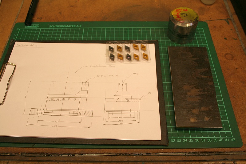
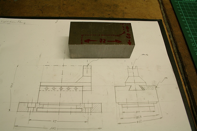
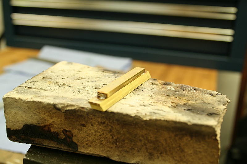
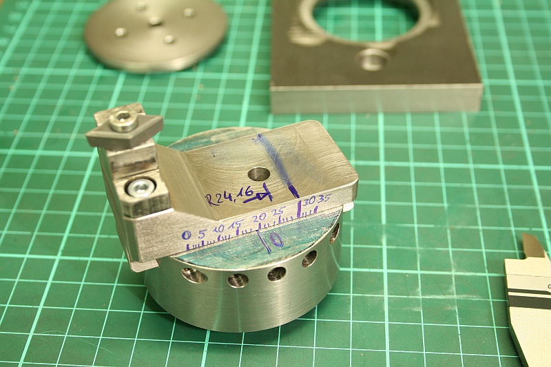
Here is a sketch, the material and the inserts:
First thing before I start to show the project itself: This ball turner is a bad design – It interferes with the workpiece and chuck all the time, it is hard to turn a 3/4 ball in one setup – Don’t built it that way! Better look into the Radford ball turner or come up with something else
Prior to this project I had to turn balls and radiused workpieces with form tools, hand gravers and by shaping with a file – So I decided that it is time to build a proper ball turner. I choose the design that Steve Beldair shows on his Website. I had a bunch of DCMT09 inserts that I wanted to use. One feature that I have not seen very often is a scale on the ball turner to set it to the desired diameter.
Here is a sketch, the material and the inserts:
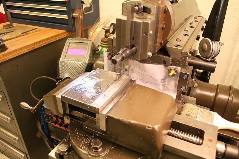
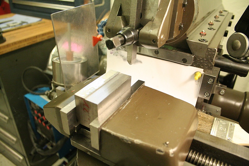
The baseplate is a piece of hot rolled mild steel – I squared it up on the shaper:
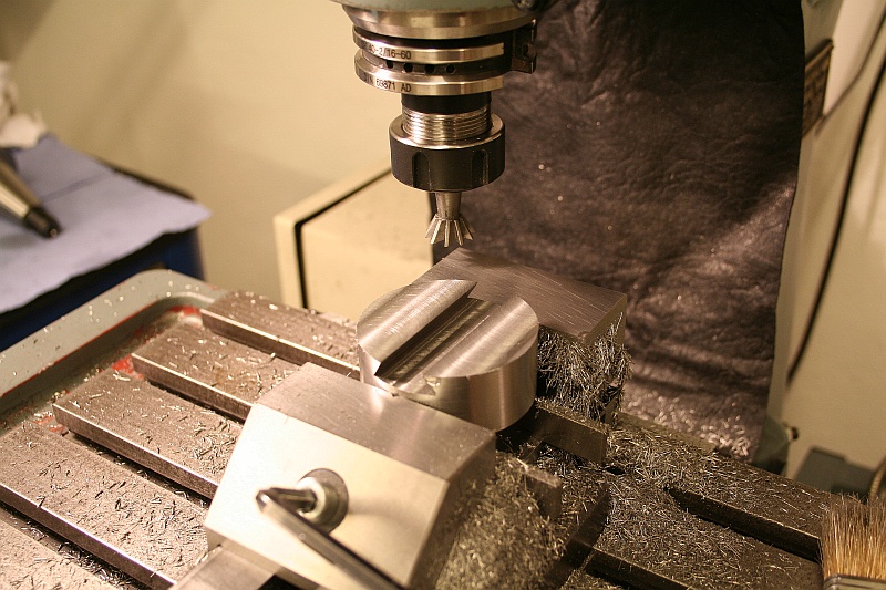
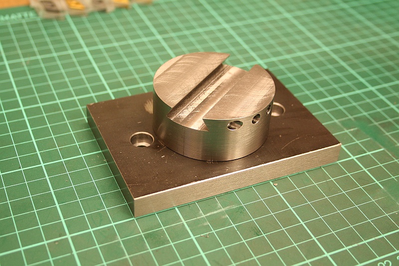
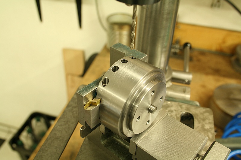
Before I continued with the baseplate I had to machine the rotating part of the ball turner – Its machined from a piece of carbon steel, the dovetail for the slide is milled in and the holes for the gib screws are drilled and tapped:
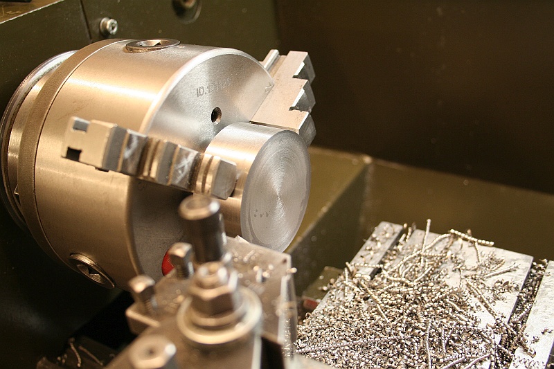
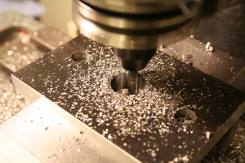
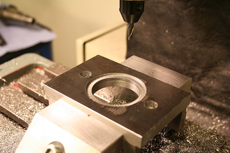
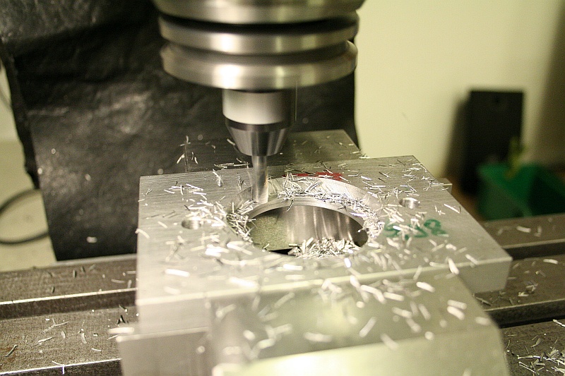
Then I could continue with the baseplate – The central bore was roughed out with a 6mm roughing endmill at full depth and 0,5mm radial engagement:
Then it was finished by boring:
The surface of the baseplate will keep its mill scale which is not suitable as a bearing surface for the rotating part, so a counterbore was machined where the rortating part can bear on:
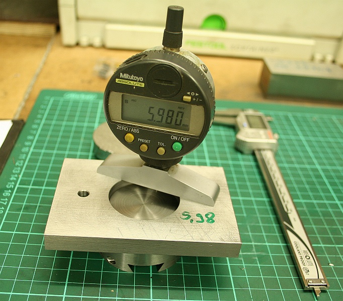
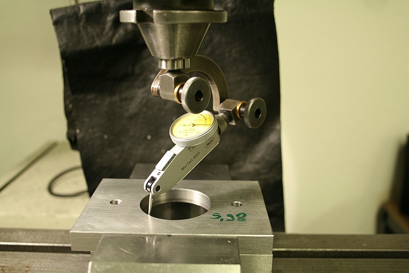
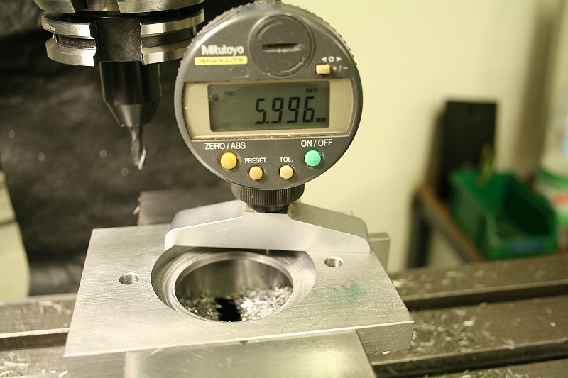
To keep the rotating part in place, the baseplate had to be counterbored from the back and a retaining plate had to be added. Here I am measuring the depth for the counterbore – I made it about 2/100mm deeper to give everything a nice, tight fit:
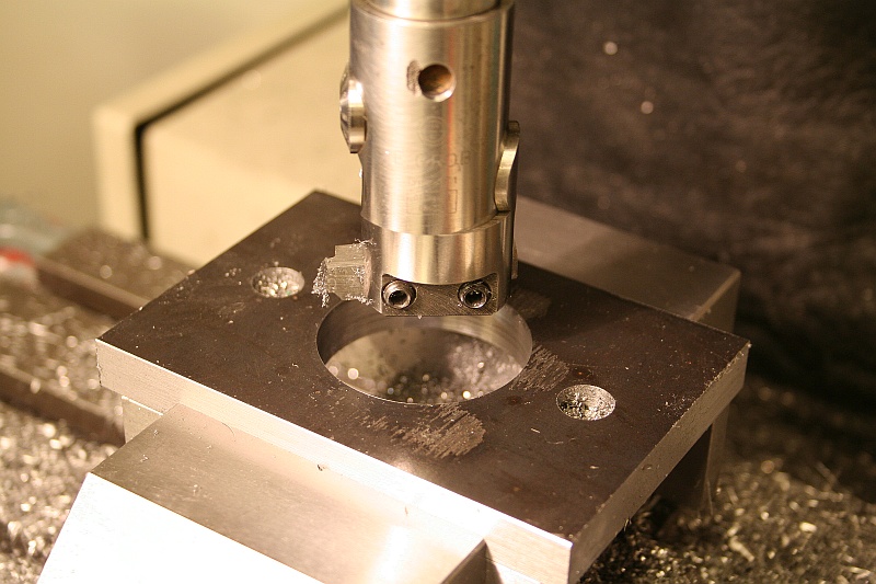
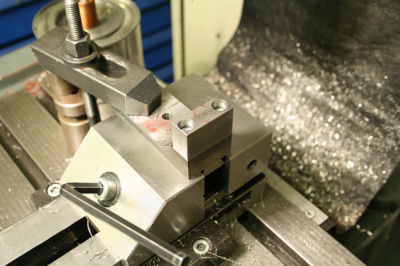
Setting the baseplate up for counterboring, checking if it sits flat in the vice and centering the spindle over the existing bore:
Milling the counterbore:
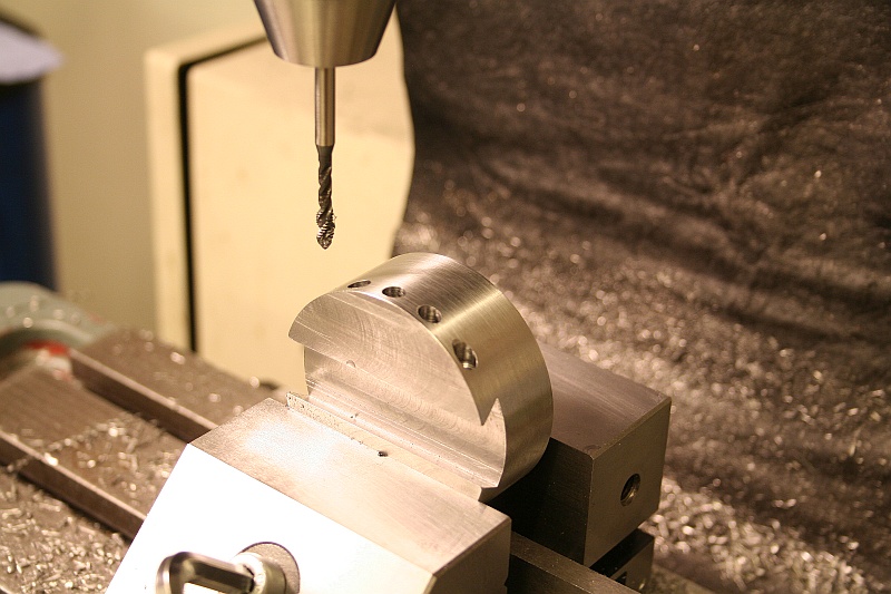
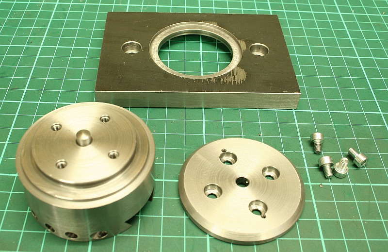
The retaining plate is a simple turning and drilling job, but I messed it up anyway ;-)
There are two extra marks from a spotting drill, where I read my drawings wrong, but they don’t do anything bad for the functionality of the part:
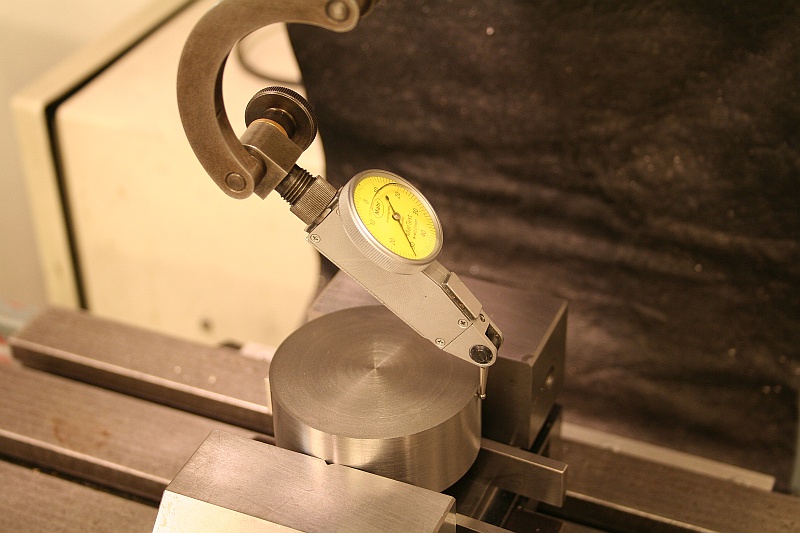
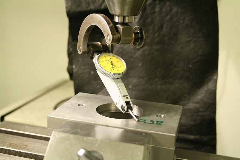
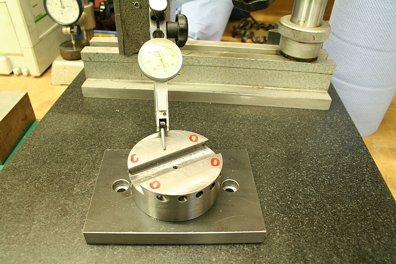
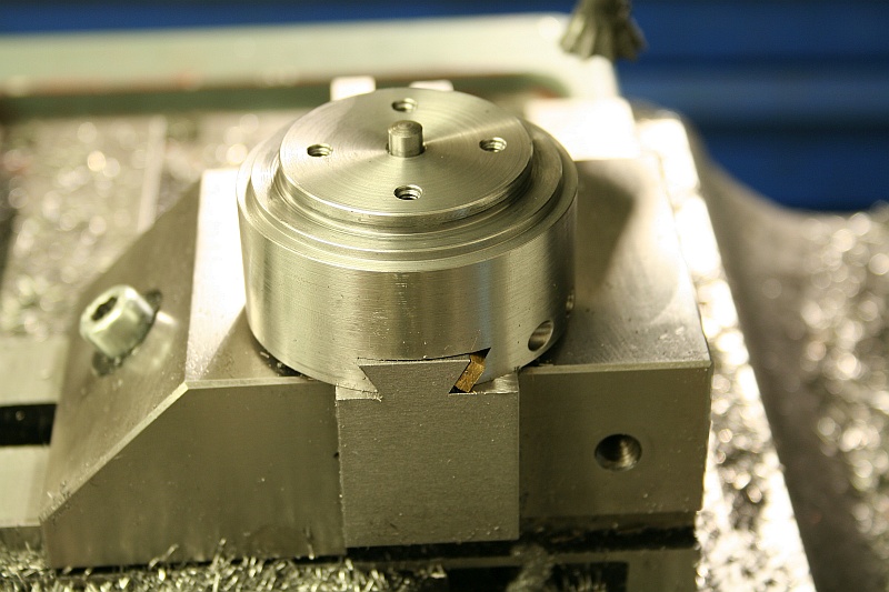
Here I was checking if the rotating part was all parallel to the baseplate – That’s not super critical, but it would be nice if the cutting edge of the tool wouldn’t change center hight during turning a ball.
But everything came out nice and accurate:
The material for the sliding part is 1.2312, a prehardened toolsteel that’s normally used for moldmaking. It’s a tough material and is very nice machining, I use it a lot for parts that I don’t want to harden but be tougher than regular steel.
I squared the block up on the shaper and sawed out the rough shape on the bandsaw:
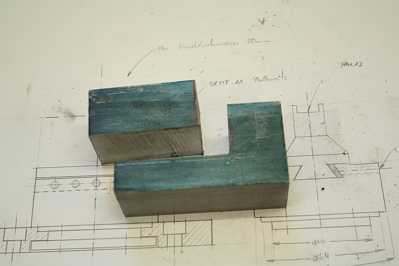
Then I finished the shape on the milling machine:

The dovetail was milled and checked with a dummy-gib for fit:
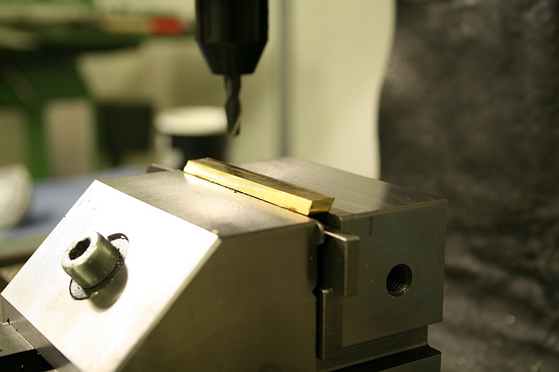
I clamped the gib with some setscrews and a piece of round stock into the the rotating part and machined the bevels on the end:
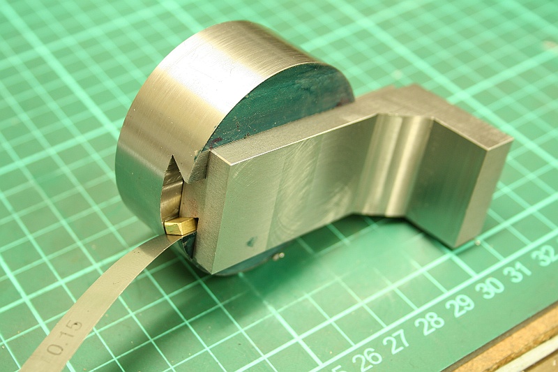
I left the gib to thick and checked the maximum thickness for it with the dummy-gib from before and feeler gages – I needed the gib to be 3,15mm thick to be a close sliding fit:
Clever as I am I machined the bevels onto the gib before I faced it to thickness – Of course the gib is now very hard to clamp…
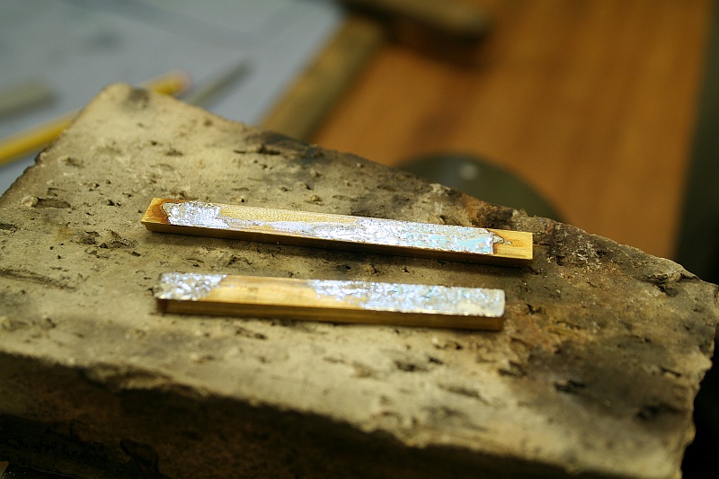
I decided to solder the gib to a square piece of brass, that could be held in the vice to face the gib to thickness. After machining the solder joint got reheated and the remaining solder cleaned off by filing:
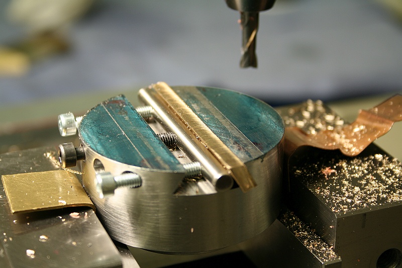
The gib was put in place and spotdrilled for the setscrews and filed to the shape of the round surface:
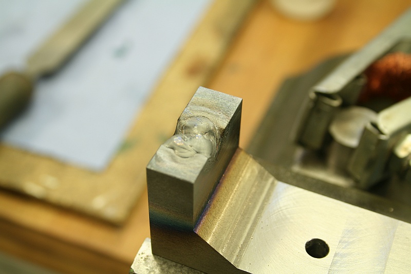
Then I Cnc-milled the pocket for the insert...:
…which went horrible wrong, it was about 1/10mm oversize and the insert was wiggling around like crazy. I tried to weld buildup the part and remachine it, but I broke a tap:
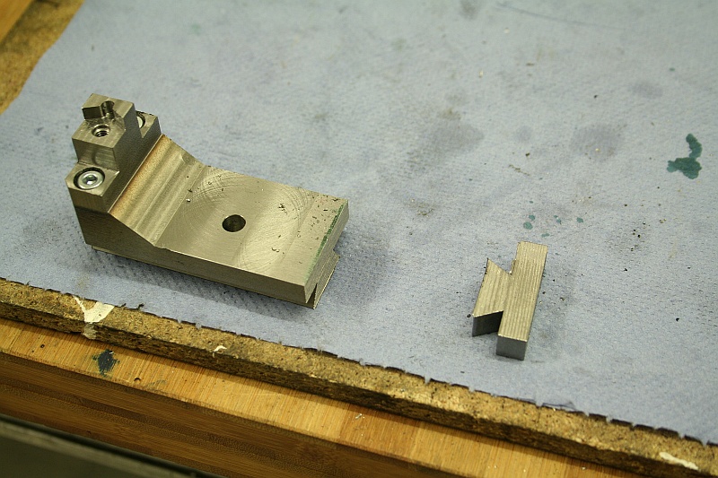
I went for a radical solution, I sawed of the upper part of the slide and fitted a new piece of steel which got screwed on:
On the lathe I measured how much had to come off to get to centerheight:
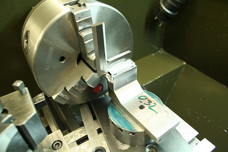
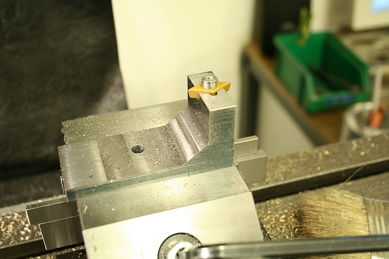
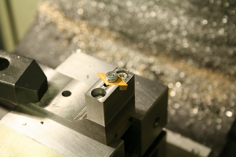
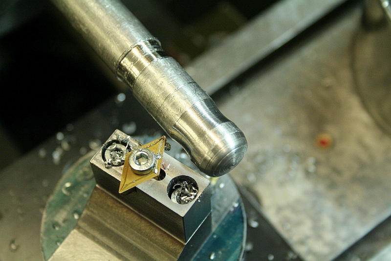
This time I went for a one-sided insert pocket. The threaded hole for the insert screw is 1/10mm offset against the pocket so the insert is firmly pushed up against the walls:
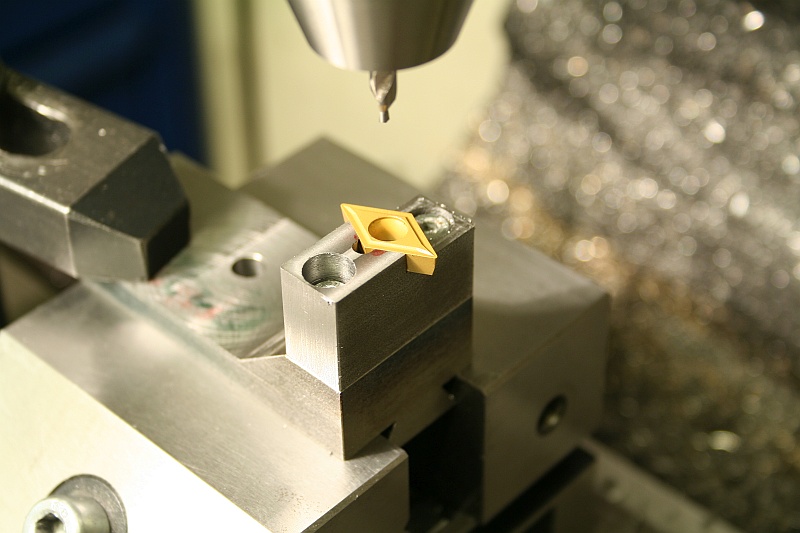
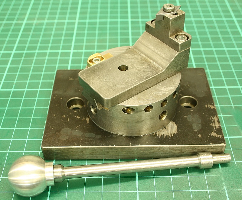
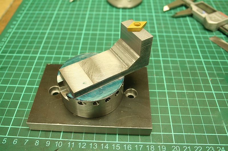
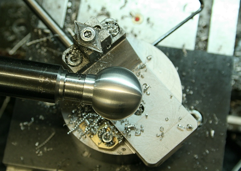
This worked very well and I could do some test cuts. What was obvious immediately was the fact that the holder for the insert bumped into the workpiece left and right very quickly. Also, the slide was way to long, it was always in danger to hit the chuck:
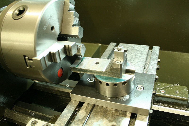
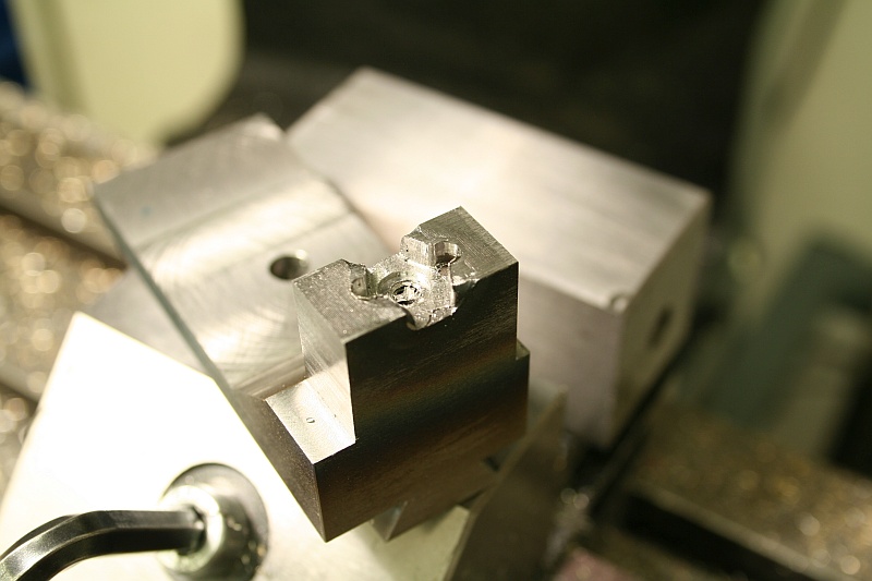
I sawed off about 10mm of the slide and milled away some material left and right to the insert:
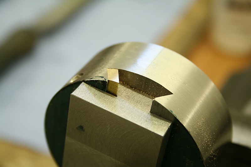
Now I was able to turn something that was almost ball shaped on the end of a piece stock:

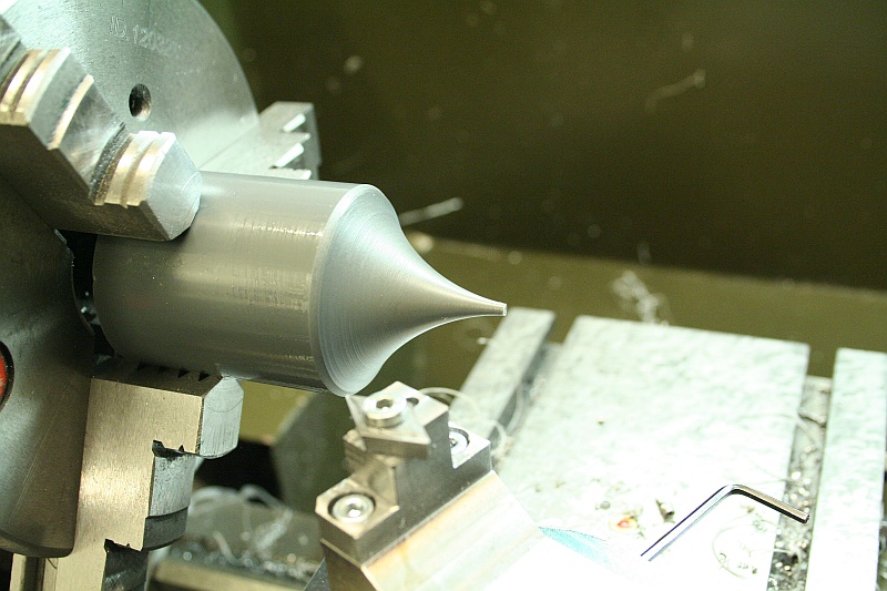
It can also do concave radii:
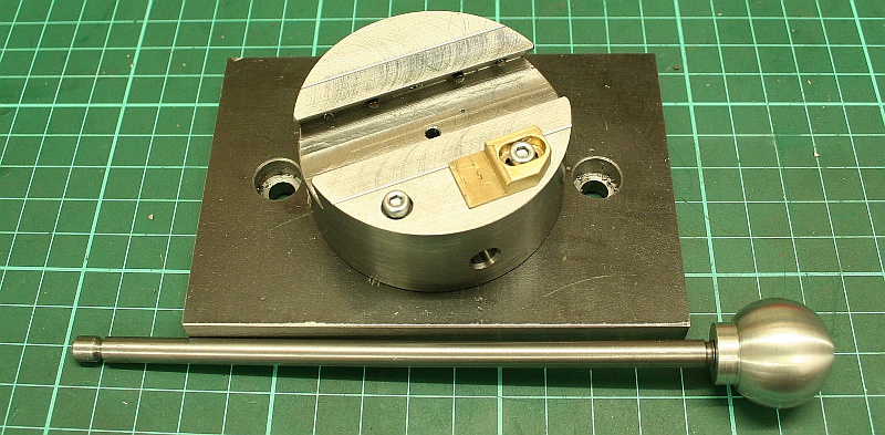
I wanted the ballturner to have a scale to set the diameter:
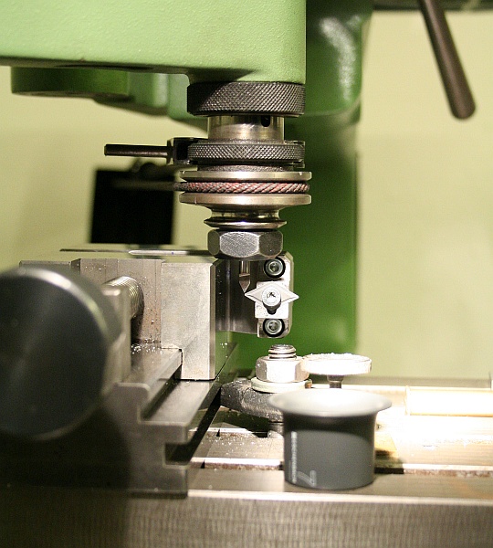
The slide was clamped on the engraving machine and the tip of the insert was picked up as the zero for the scale:
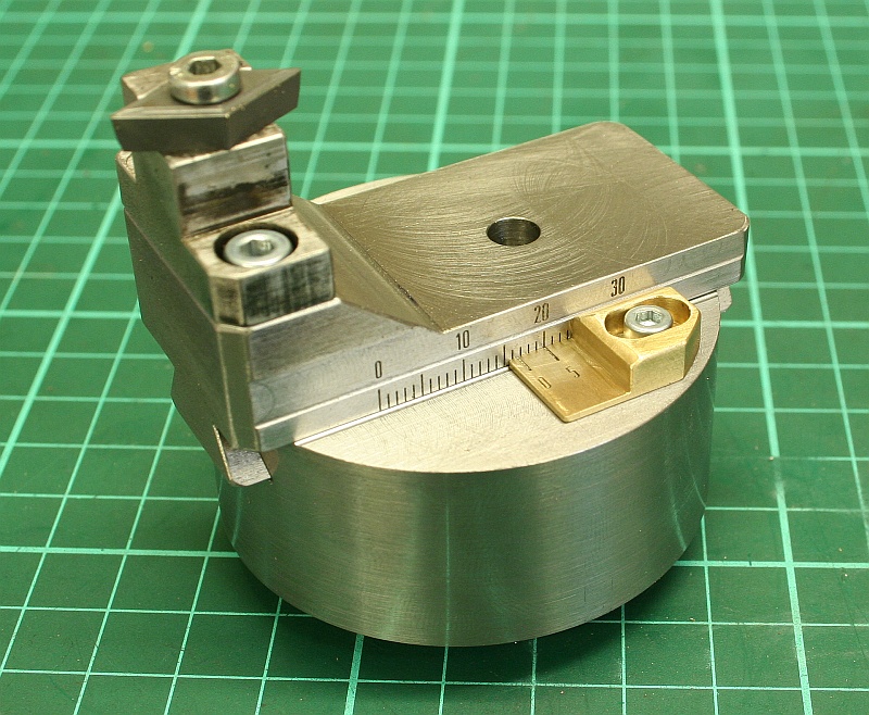
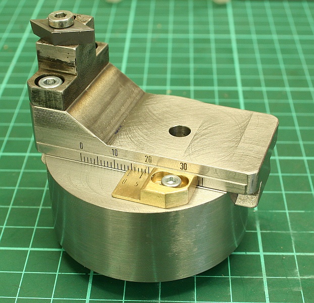
And this is the ball turner with the engraved scale and a two line vernier that can be adjusted:
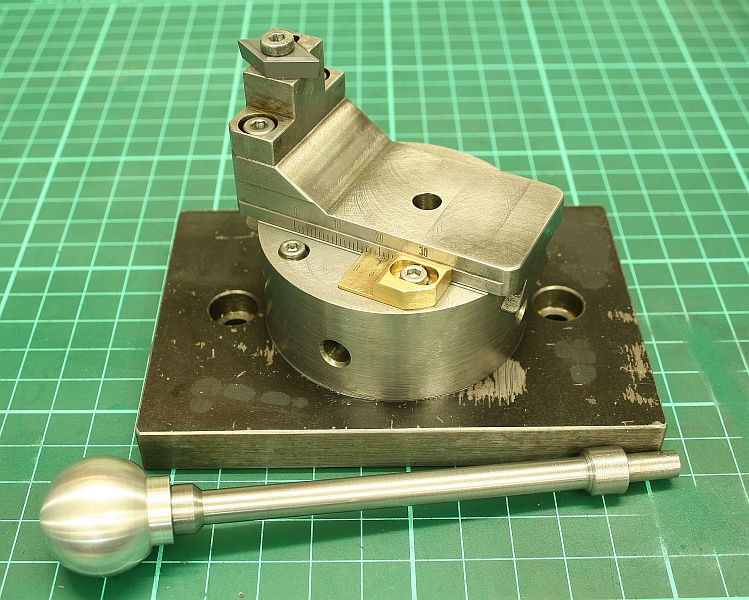
Of course, the first ball turning project is always a ball handle for the ball turner itself:
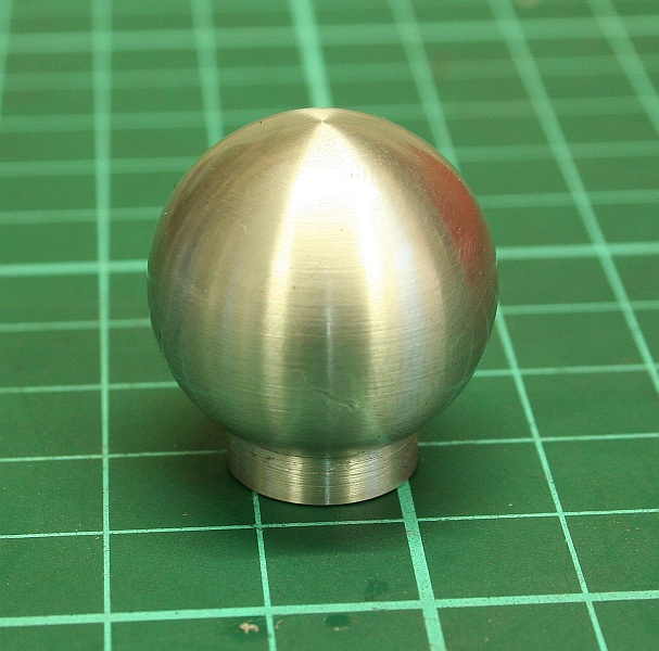
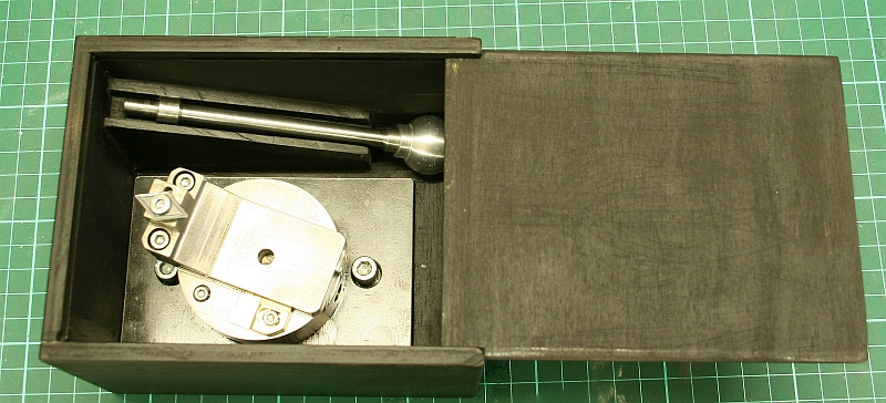
The finished ball turner with the handle and a wooden box: