While I have a toolpost grinder for my lathe that works quite well, the surface finish I get with it is nothing to write home about it. The lathe is just not built to do grinding.
But my surface grinder is!
For that reason I wanted to add the capability to grind round parts with it.
There are many (aftermarket) ways to grind round parts on a surface grinder (or an universal tool&cutter grinder):
For most of my parts, grinding between centers seems to be the best choice, as it allows to take a part out and remount it without loosing any precision, also flipping parts around is no problem. By angling the jig in a grinding vice tapers can be ground.
The precision that needs to be built into such a jig is very small, everything comes down to a part that spins between to fixed centers and aligning the jig to the axis of the surface grinder.
I did a series of videos on building and using the cylindrical grinding attachement:
Cylindrical grinding attachement - Part 1
Cylindrical grinding attachement - Part 2
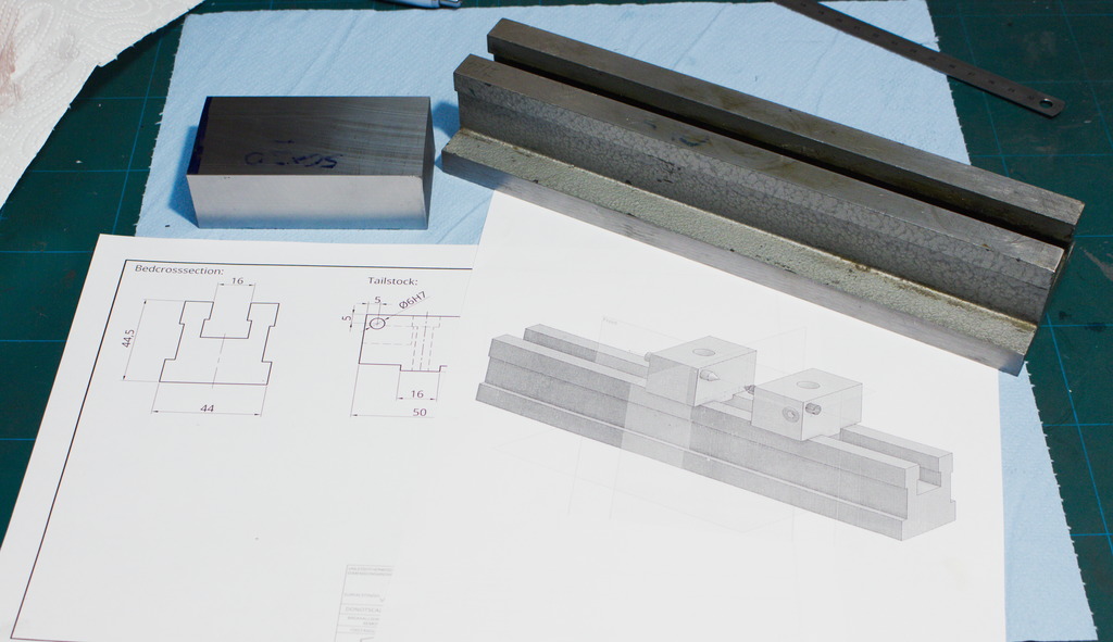
This is a crude mockup of what I am going to build. The base for the jig is an old indicator stand. Two tailstocks will be built, that carry dead centers, one of them needs to be spring loaded to compensate for heat grow. The work will be driven by a small DC-motor:
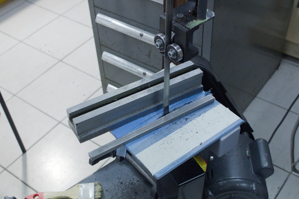
I started by cutting down the bottom flange of the indicator stand, to make it a bit lighter and easier to handle:
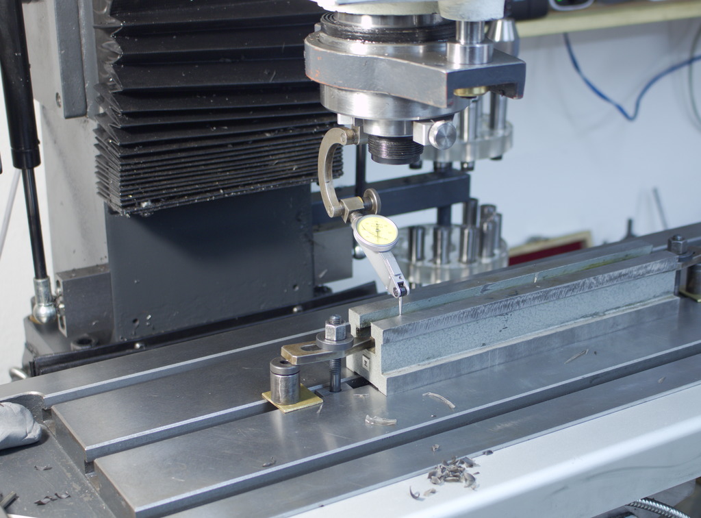
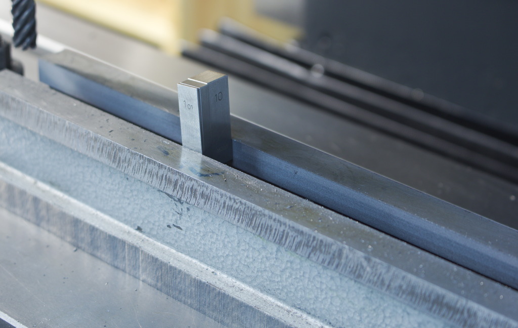
The t-slot of the indicator stand gets finished to 15.01mm, then it is flipped around, indicated in and the rough sawn surfaces also machined true to everything else:
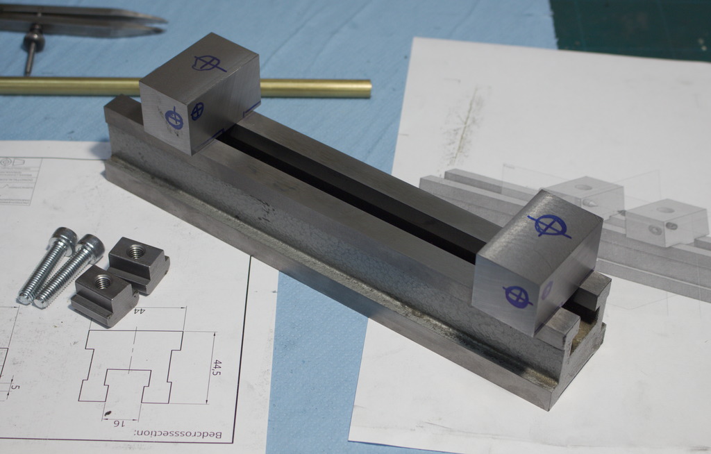
The two tailstocks have a key milled on their underside and will get clamped to the base with two M8 screws and two stock t-nuts:
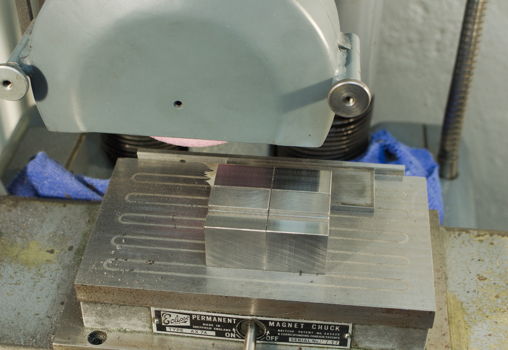
I surfaceground the surfaces that bear down on the indicator stand:
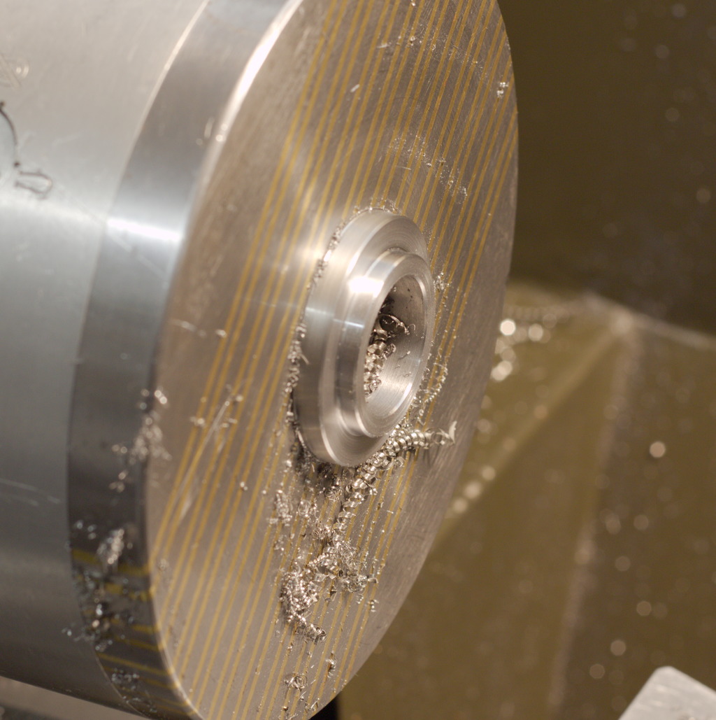
Drilling and reaming the 6mm holes (6H7) for the two dead centers. The hole in one was reamed to be a very close fit, the other one is ground to a sliding fit:
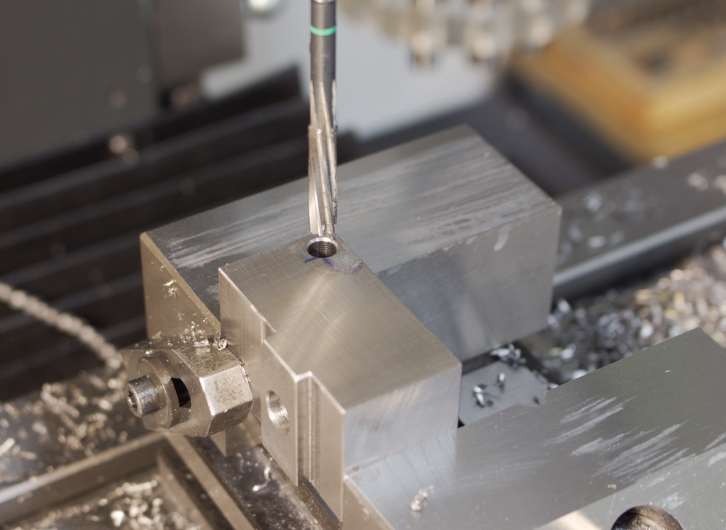

I used the quill powerfeed for reaming and the surface finish with such a even feed is way better than handfeeding a reamer.
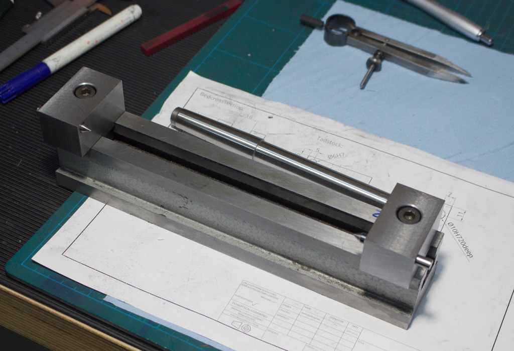
The attachement with the two tailstocks:
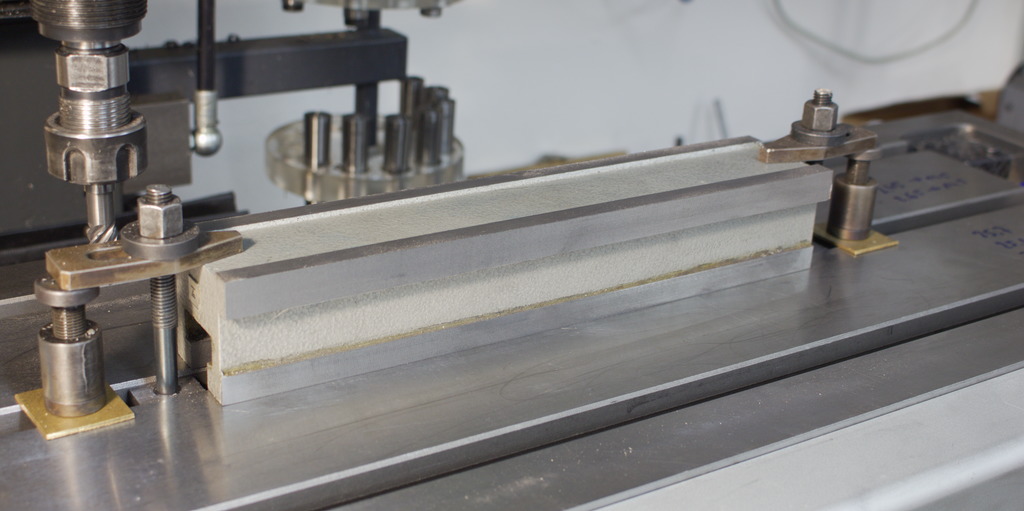
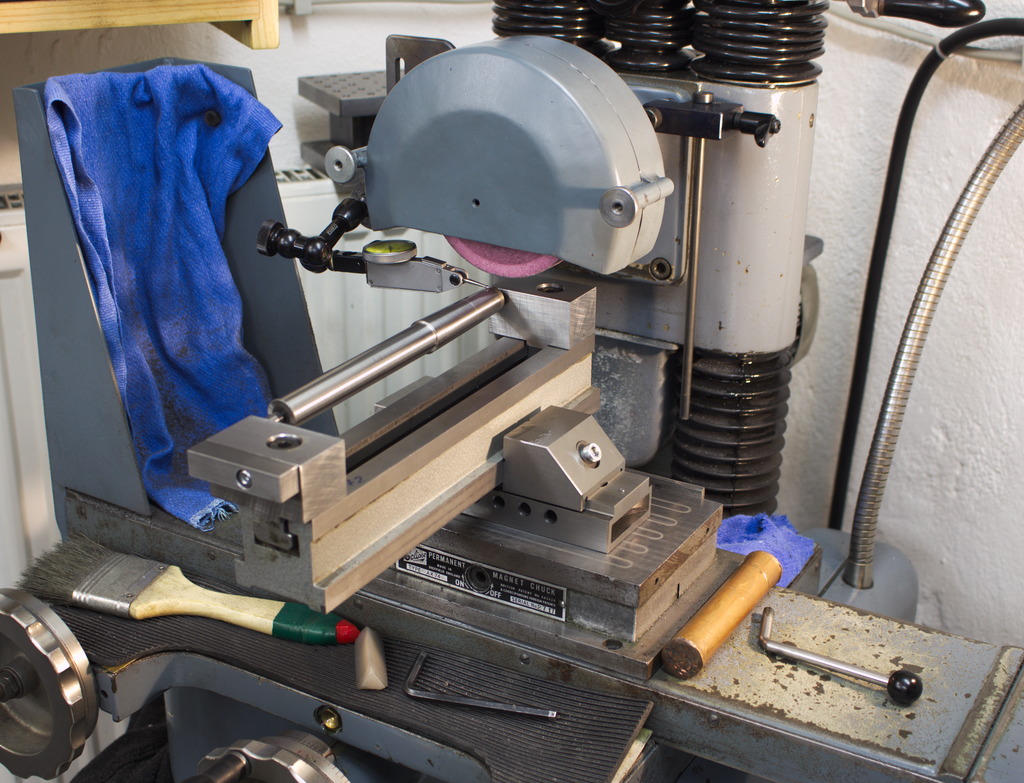
To grind tapers, a master taper (In this case a MT2 testbar) is setup and an indicator is ran along the taper and the attachement is tilted in the vice until the indicator reads zero back to front.
On the rear of the front tailstock (operator side), a block can be seen. This block houses a strong spring which preloads the dead center:
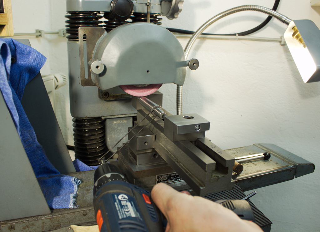
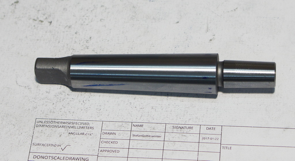
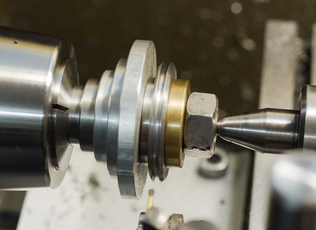
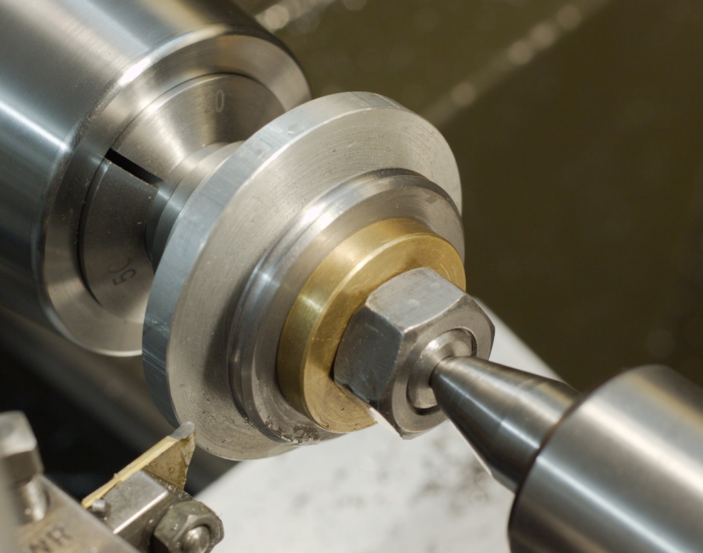
Before I started to build the drive train, I gave the attachement a testrun with the cordless drill and an O-Ring, regrinding a MT2 drillchuck arbor. The surfacefinish on the MT is just as good as the factory finish on the drillchuck taper:
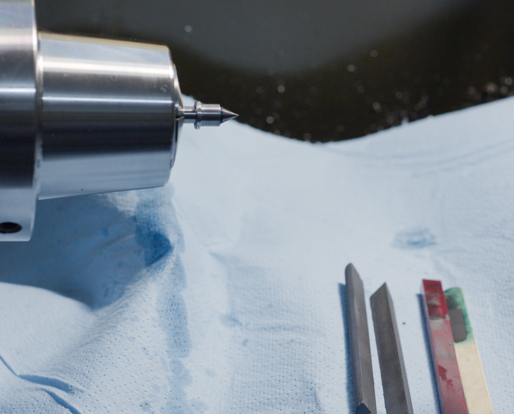
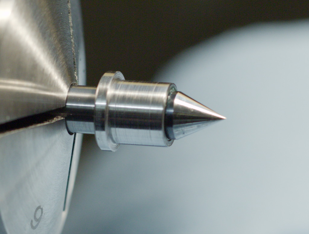
The carbide centers where ground on the single lip cutter grinder, but a better surface finish helps to protect the center in the part to be ground from wear, so I polished the centers with silicon carbide stones and diamond lapping compound on a piece of wood:
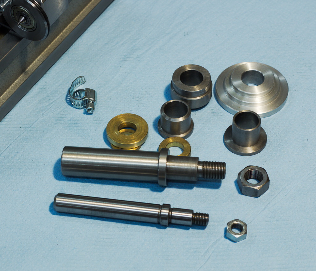
Machining the pulley that spins free on one of the fixed centers:
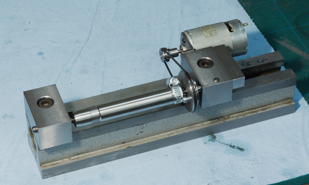
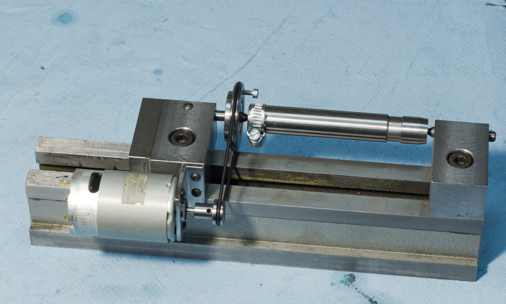
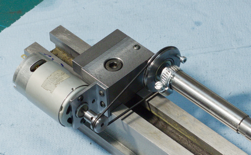
The finished grinding attachement with the drive motor (The endcap for the motor is still missing).
The drive consists of a disk that spins freely with a ball bearing on the spring loaded dead center. The screw in the drive disk drives the work via a dog (In this case just a hose clamp).
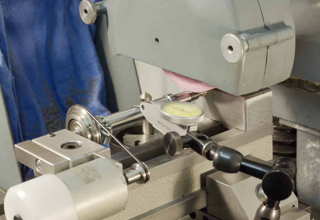
Setup on the surface grinder, with the drive motor:

Typical work that can be done on this kind of grinding attachement, lathe arbors. I made the bigger of the two arbors long time ago and it gets used quite a lot on the lathe to hold parts that have a trough hole - I machine bushings if the hole in the part is bigger than the arbors diameter.
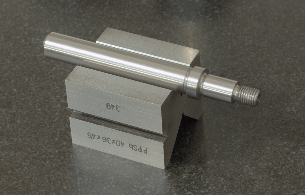
I don't have such an arbor for smaller work, so I turned one from dril rod and hardened it to 40..45Hrc to be used as a test piece for the grinding attachement:
The finished arbor after grinding, ready to be used. I checked the runout of it by spinning it in the v-block, and everything is well under 4/1000mm (thats ~4/10000"):