Indicator stands – I am not a real fan of most central locking, free adjustable indicator stands. They have a few flaws that make them relatively annoying to use for precision work. For example the lack of rigidity, the articulating arm has a very small cross section where it connects to the magnet and that is a weak link. The fine adjustment on most of them is also not very good, they are not free of play, some have even backlash and most of them are very coarse to adjust.
The well known Robin Renzetti showed an indicator stand that he built several years on Instagram:
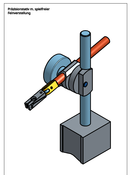
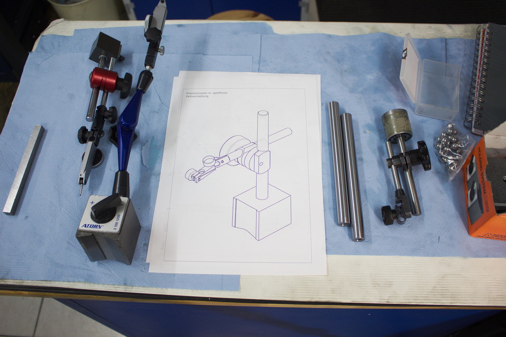
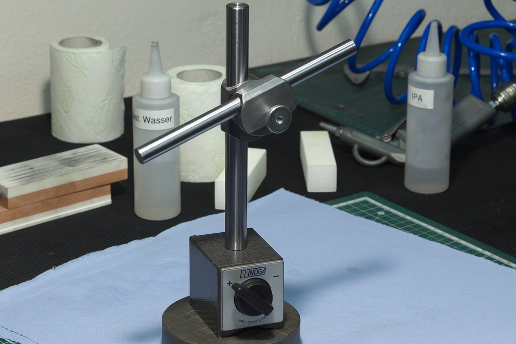
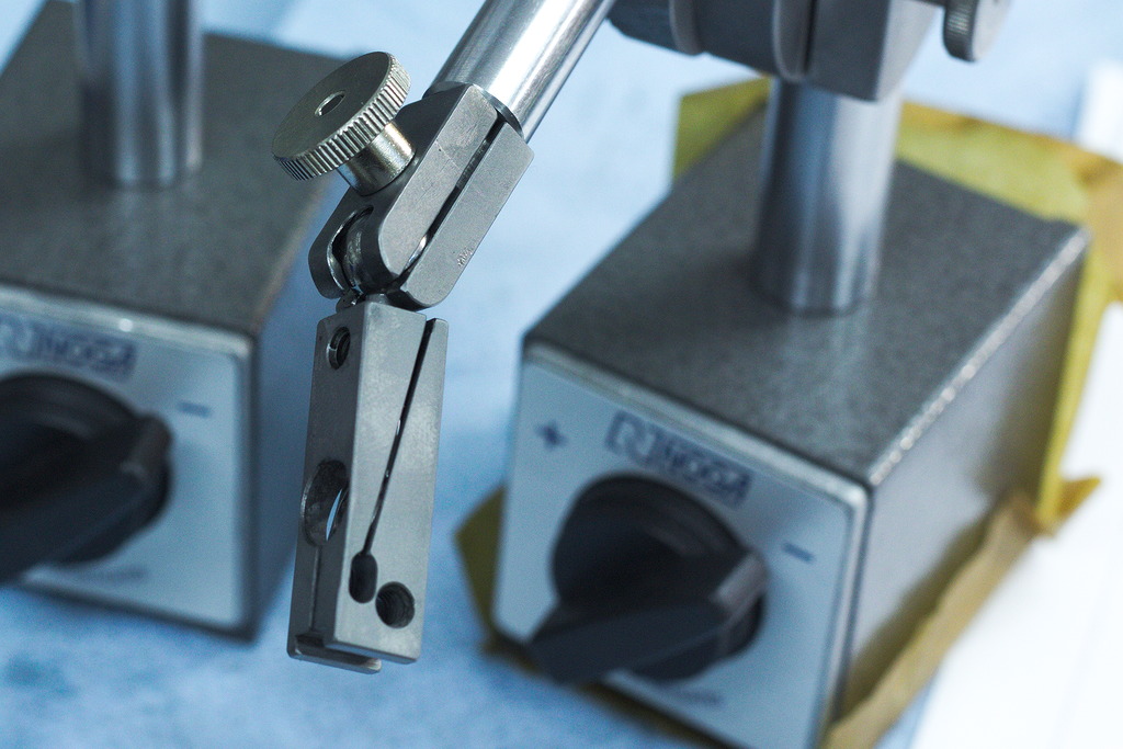
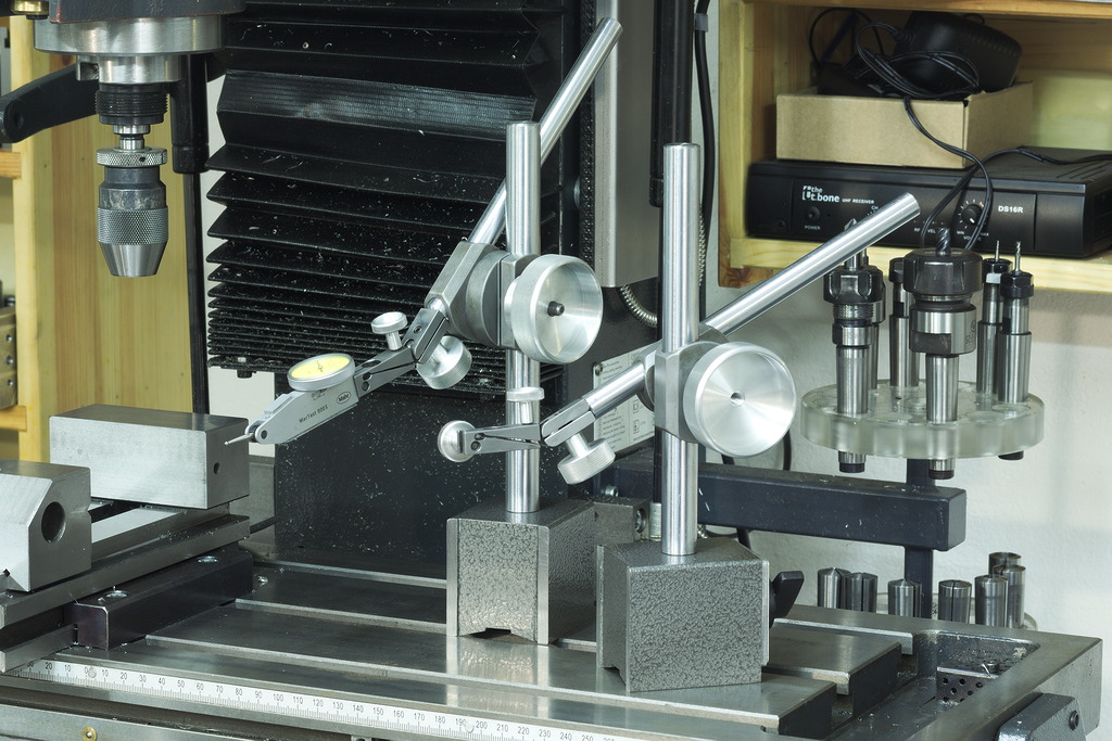
Indicator stand - Overview
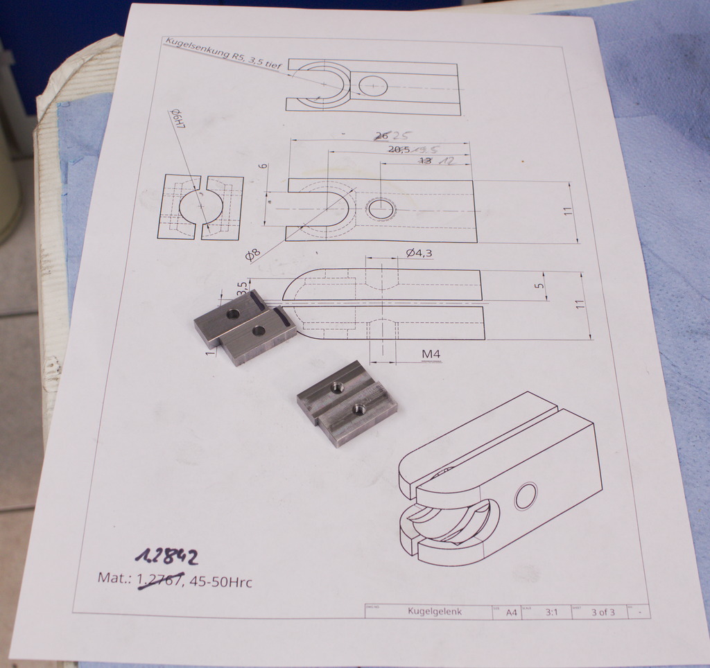
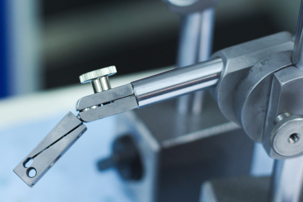
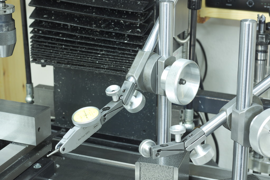
Indicator stand - Ball joint design
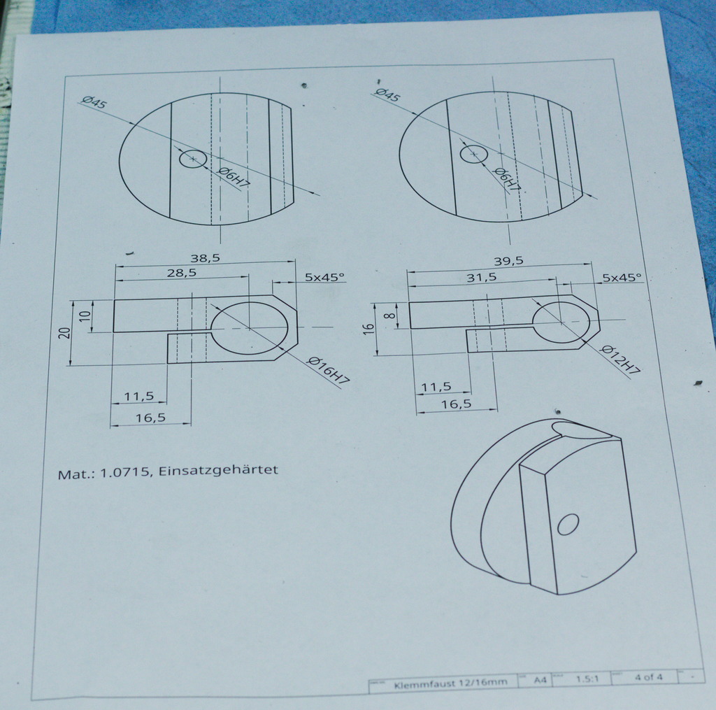
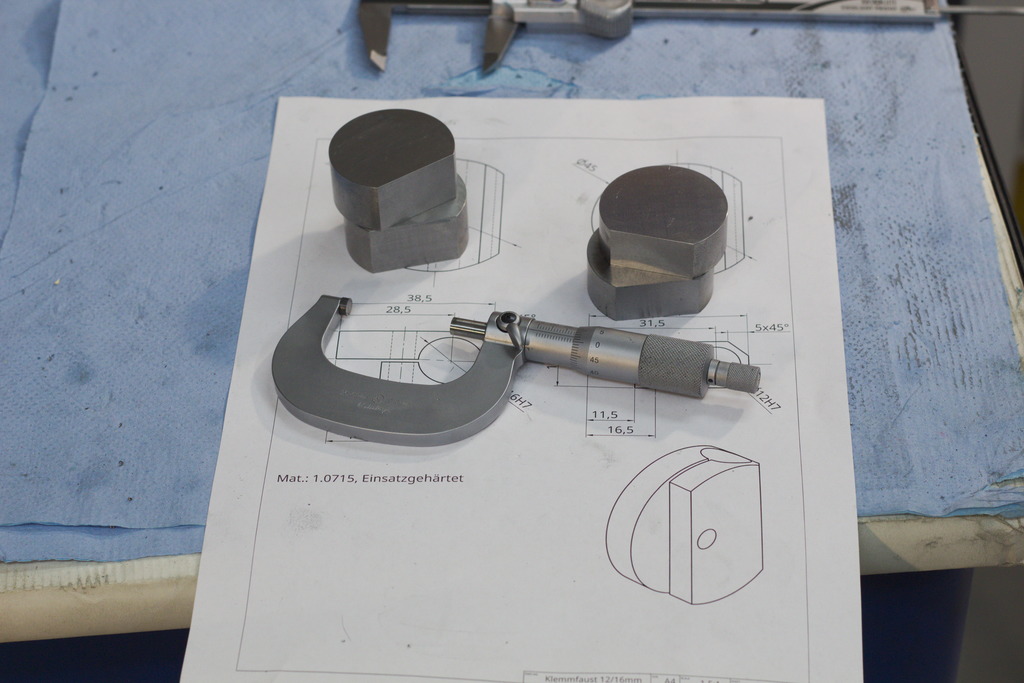
His design made me want to build something similar and I started to draw something up, first by hand and then in Onshape:
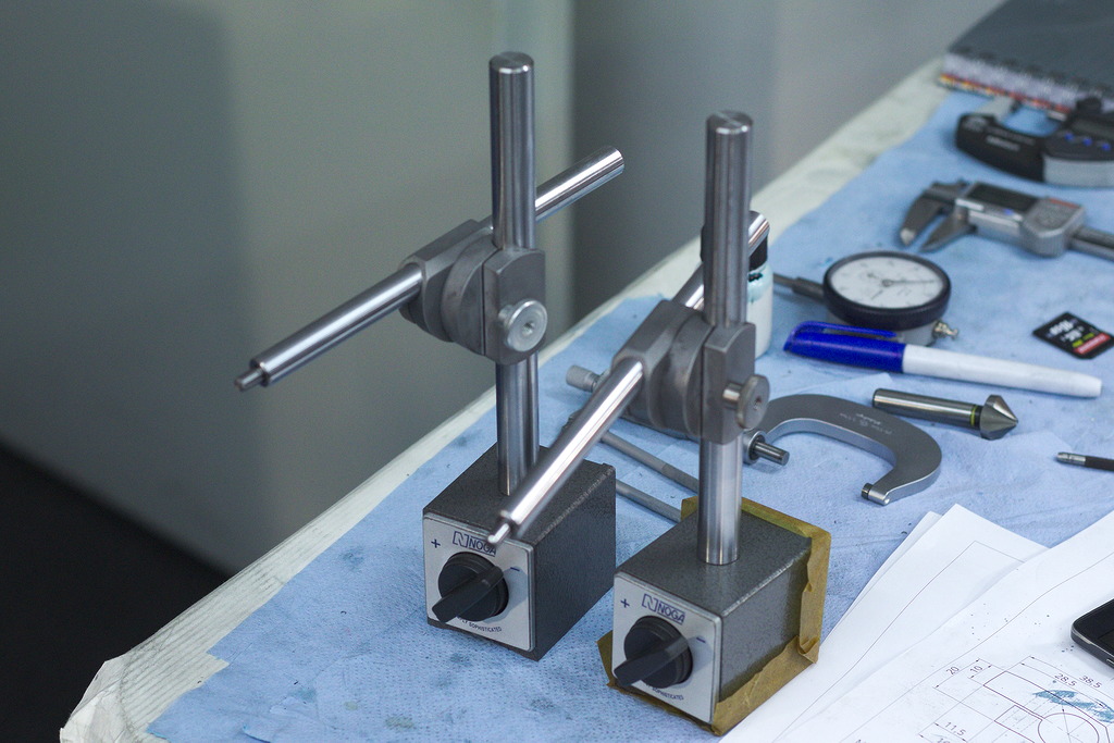
I planed to make two of the indicator stand, so I ordered two magnets from Noga and hardened/ground linear shaft material in 16mm and 12mm diameter.
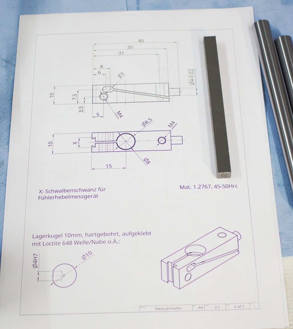
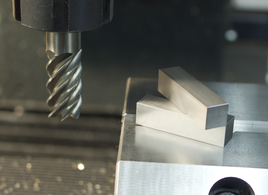
The first part machined will be the combined indicator holder and fine adjustment mechanism. It is machined from 1.2767 toolsteel and will later be hardened to about 45..50HRC:
Cut to size and machined to the final dimensions. Hobbyists often worry about the machineability of toolsteels, but the truth is, that even highly alloyed toolsteels can be machined quite well, but some will wear tools down a bit faster than other.
The 1.2767 I choose for this part machines quite well and is not to hard on tools.
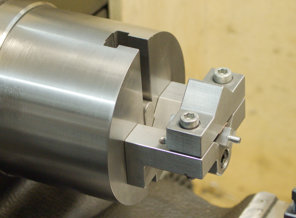
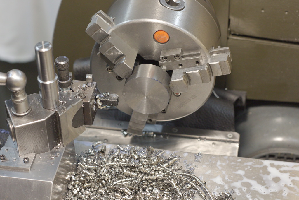
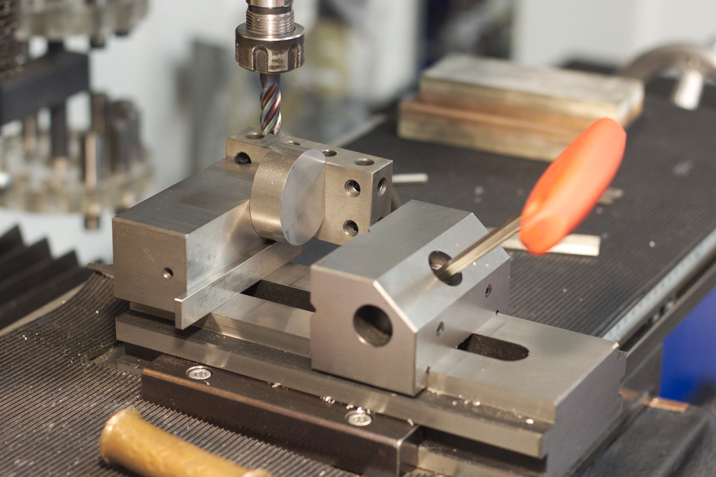
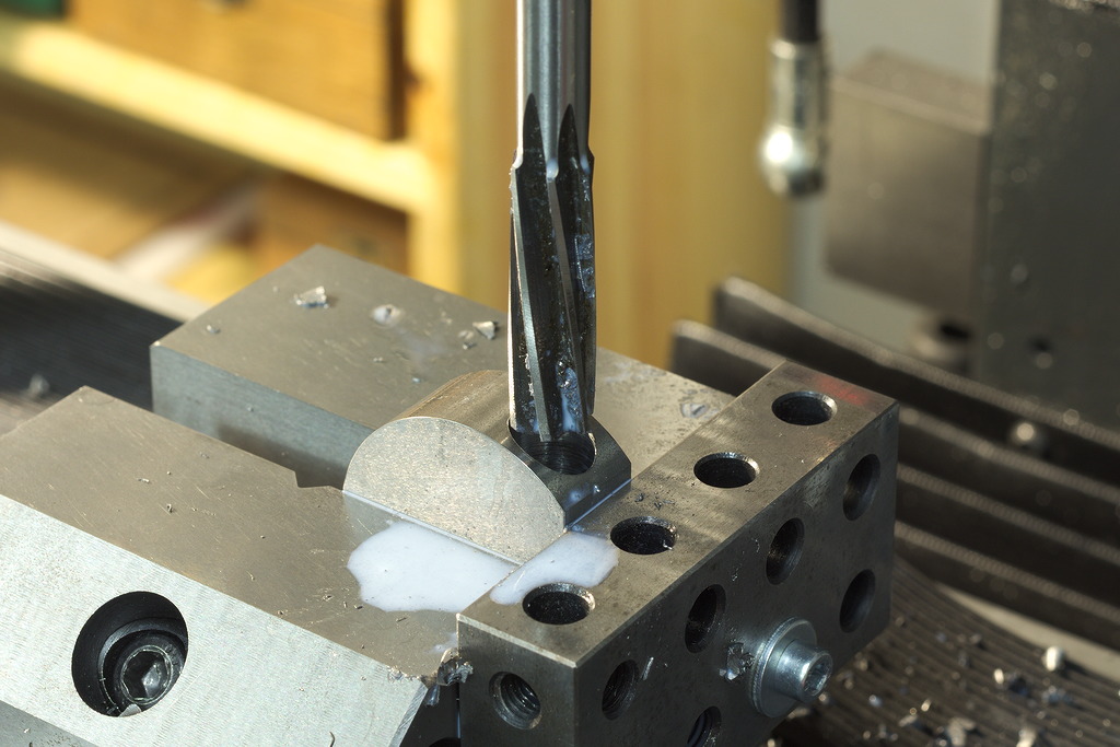
With the v-block chuck, the part is setup to machine the cylindrical end that will hold the ball for the balljoint:

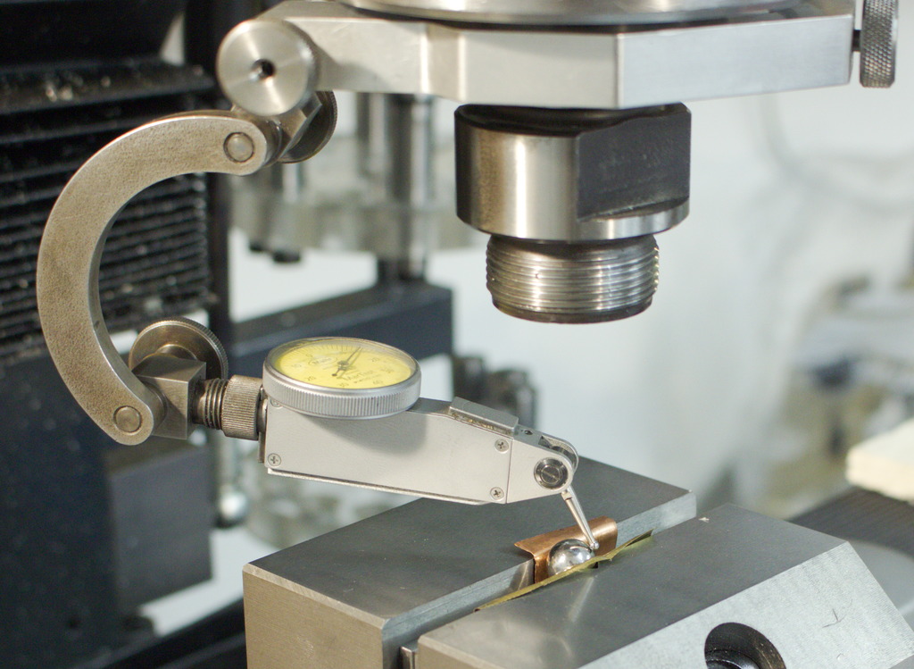
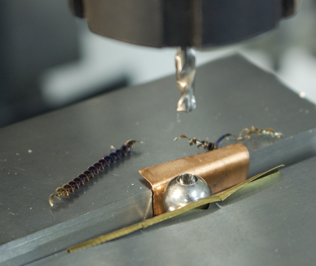
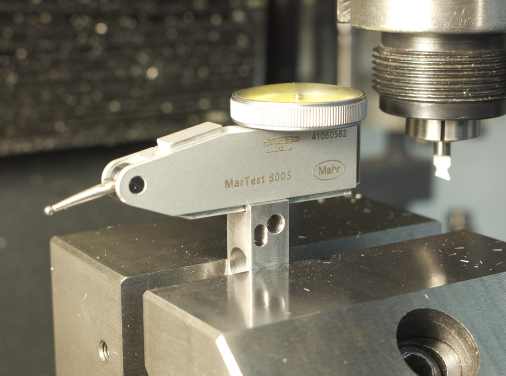
Harddrilling a 10mm bearing ball for the balljoint. Centering with a dial test indicator, the ball is held between soft shimstock, so it does not damage the vice jaws.
Drilling hardened materials with a carbide drill leaves generally a very clean and close tolerance hole, which is in this case a light press fit on the cylindrical end of the indicator holder.
The ball will later joined permanently with loctite 648 to the indicator holder.
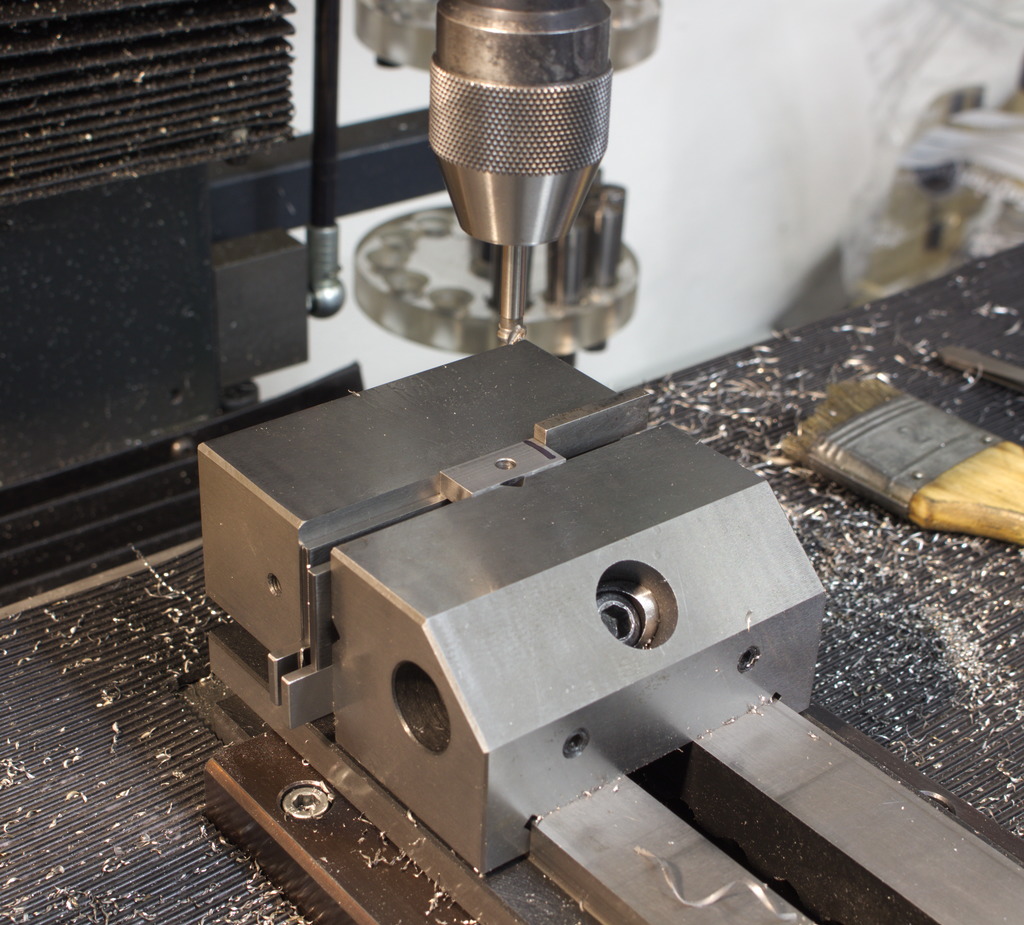
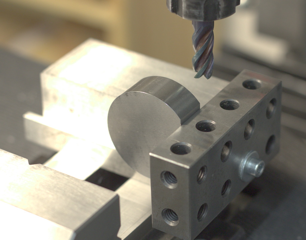
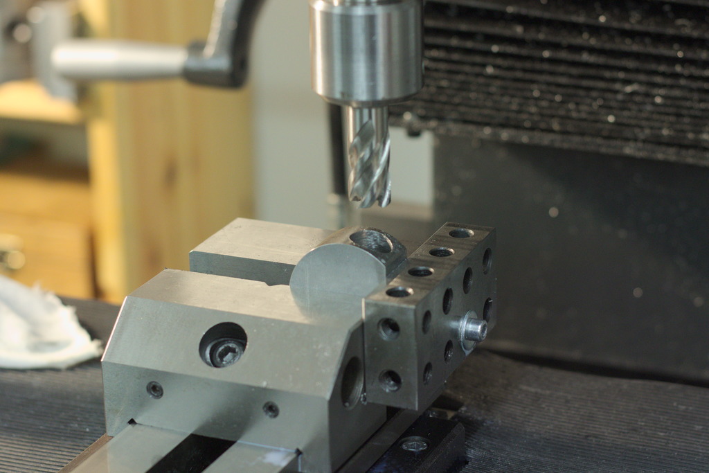
Doing all the drilling and milling work on the indicator holder. The flexture has a slot in the end – a first design just had a 3mm hole, but as Robin pointed out, that will result in a stress rise area which can cause a break.
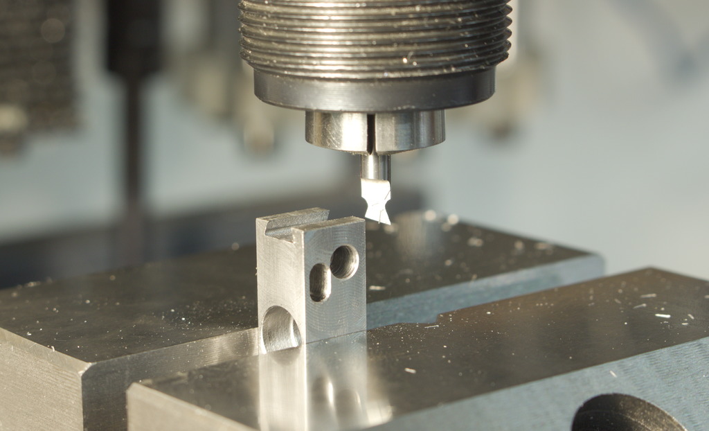
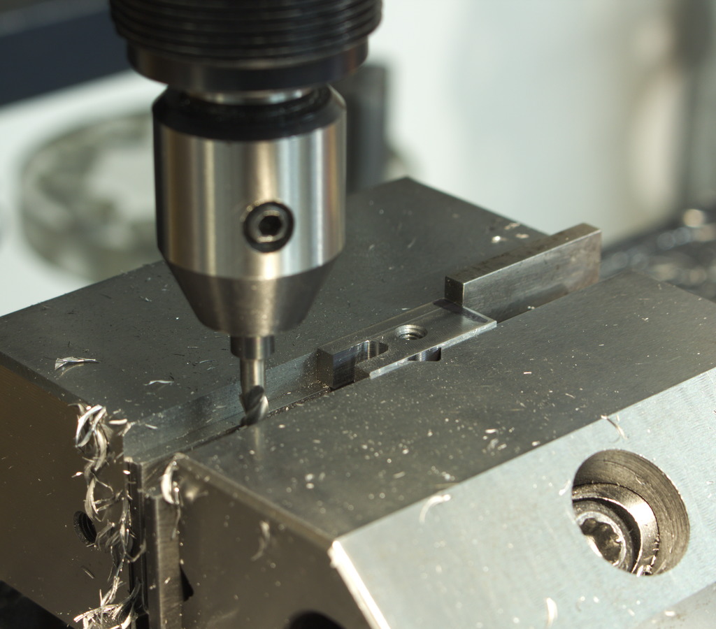
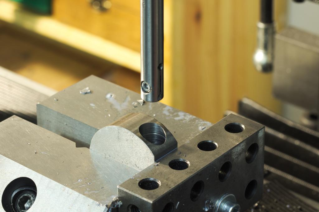
Milling the flexture slot was done with a long (relieved shank) 3mm carbide endmill, with the end of the slot predrilled on one end, taking only 0,5mm deep cuts.
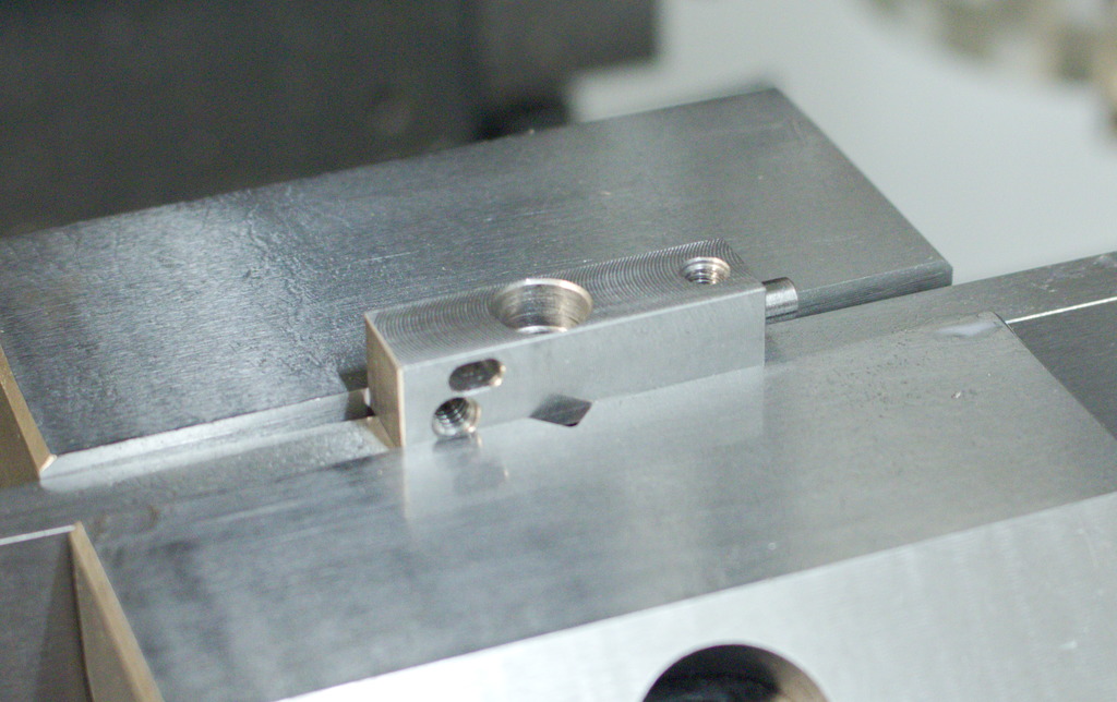
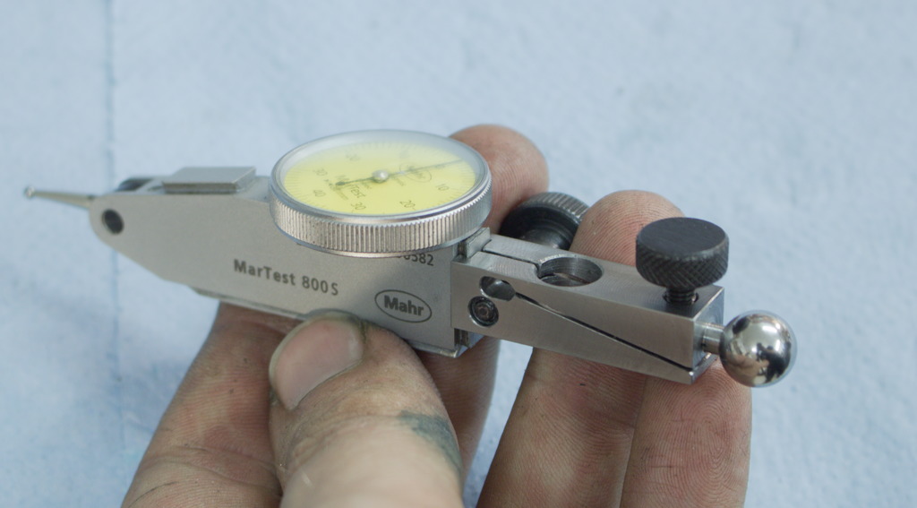
Here I am machining the small dovetail slot for the dial test indicator. When doing this, be carefull, the tolerances between indicators can be quite loose, when one indicator fits nice, the other one can be very tight. In this case it is not much of a problem, as the clamping part is very flexible.
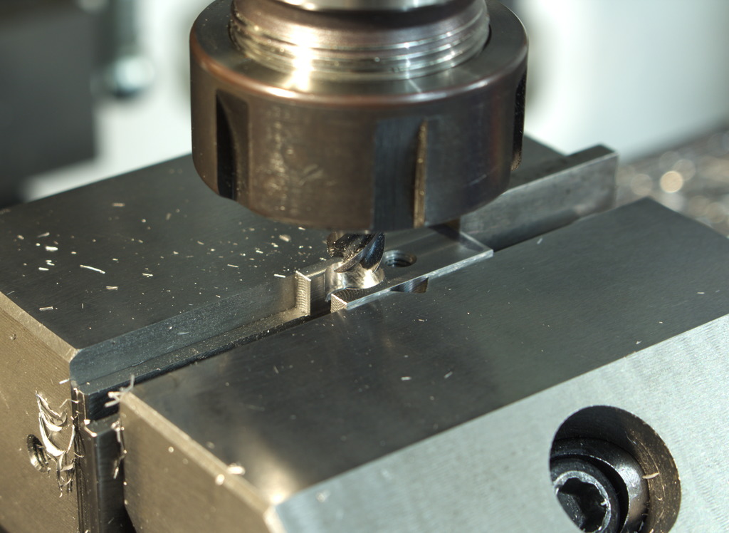
Cutting the flexture slot for the fine adjustment and for the clamping mechanism of the indicator – The carbide sawblade I used could not reach all the way trough, so I finished the cut by hand with a narrowbladed hacksaw.
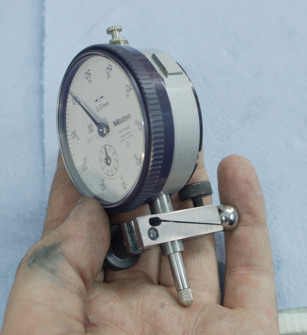
The indicator holder can not only hold dial test indicators with a dovetail but also normal indicators with an 8mm shank. The fine adjust works with the indicator too, as the 8mm hole is relieved to a diameter of 8,5mm in the fixed portion of the flexture.
The next part made is the balljoint – It consists of two parts that clamshell around the ball and the cylindrical end of the rod on the stand.
The drawing calls also for 1.2767 toolsteel, but I had only 1.2842 (O2) toolsteel, which will work just as well, I just have to take this into account when doing the heat treat.
The clamshells get a series of drilling/milling operations to get them to the final shape. The shape for the 10mm ball gets formed with a ball endmill.
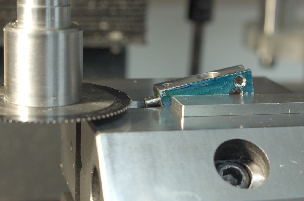
I glued a stop to the fixed jaw of my vice to batch out all the operations.
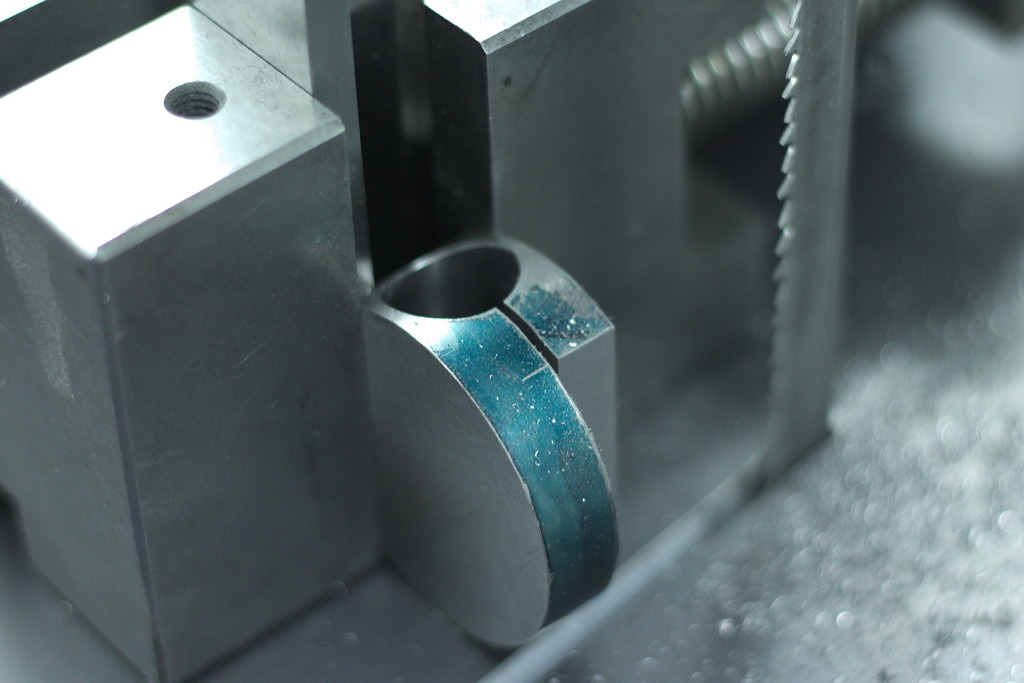
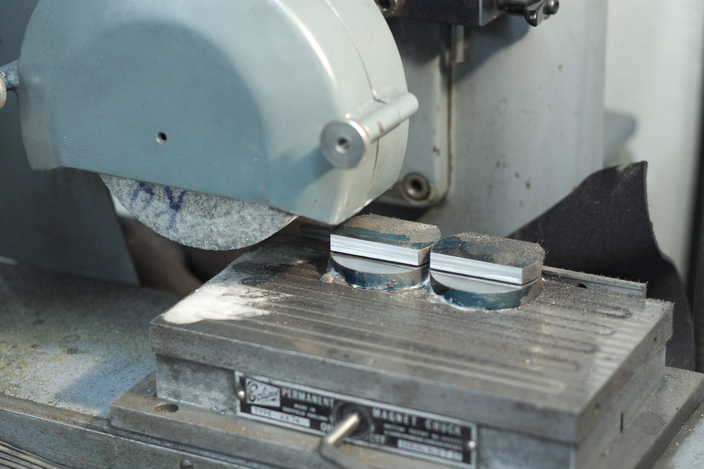
Surface grinding the split line of the clamshell parts to make them actually clamping on the ball and the cylindrical part.
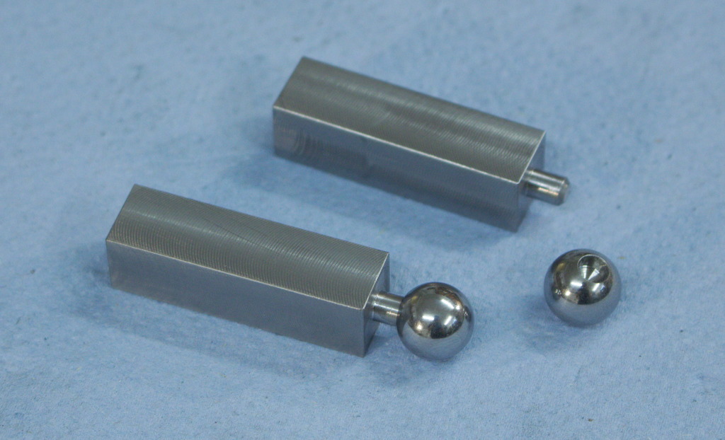
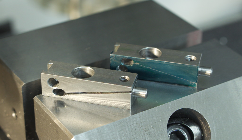
The finished indicator holder and ball joint minus the heat treat and finishing.
One note about the ball joint – The way I machined the parts the clamshell clamp is overconstrained , it could happen that only the cylindrical part gets clamped or only the ball gets clamped and one or the other element can wiggle.
Robin accommodated this by relieving the cylindrical bore in the clamp to form a three point support, it is shown in his short video on Instagram
For some reason I don’t have this problem with my clamp – I guess by machining the rear cylindrical bore with a ball clamped between the clamshell parts, it got precise enough and with the elasticity in the part it can conform so much to clamp everything securely.


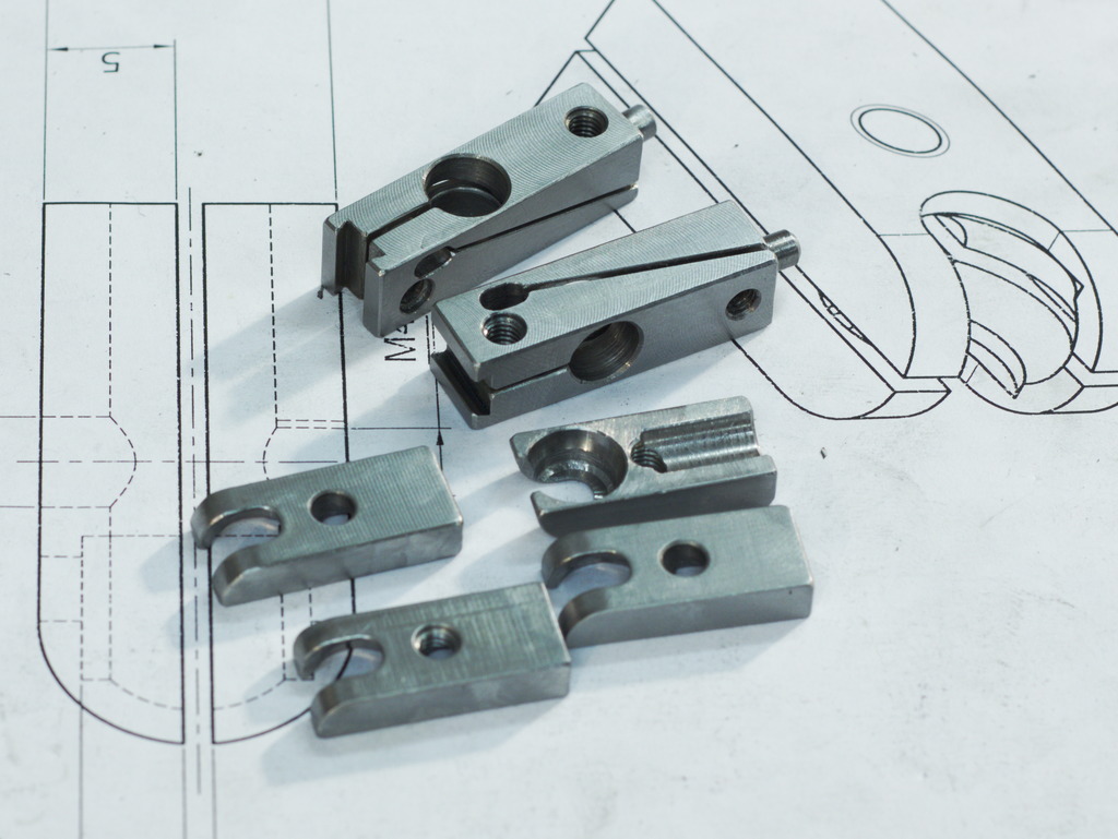
Two of these parts together will form the central clamp for the rods of the indicator stand. They are quite similar, main difference is that one is drilled/reamed 16mm, the other one 12mm.
I did’t have toolsteel that large, so I decided to make the parts out of free cutting mild steel and case hardem them later.
To be realistic, the parts would work perfectly fine without any heat treat too, but I want to make them more durable against wear and tear in the shop.
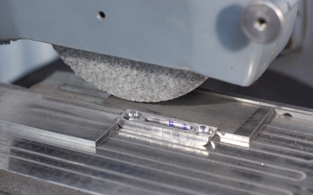
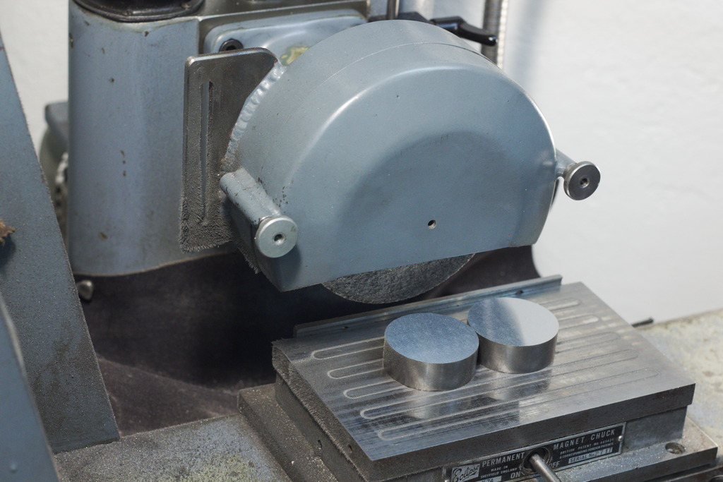
The bandsawn blanks get faced and surface ground to thickness:
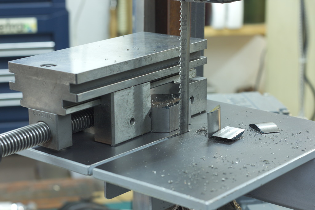
Cutting away excess material on the bandsaw – Note the grinding vice holding the part for sawing. This is a very safe way to handle parts on the bandsaw.
The bandsawn surface gets cleaned up on the surface grinder:
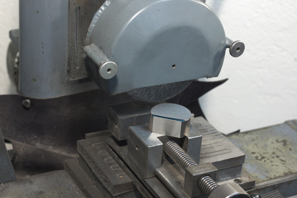
Using a large block screwed against the side of the vice forms a nice large profile stop that aligns the flat of the parts verticaly.
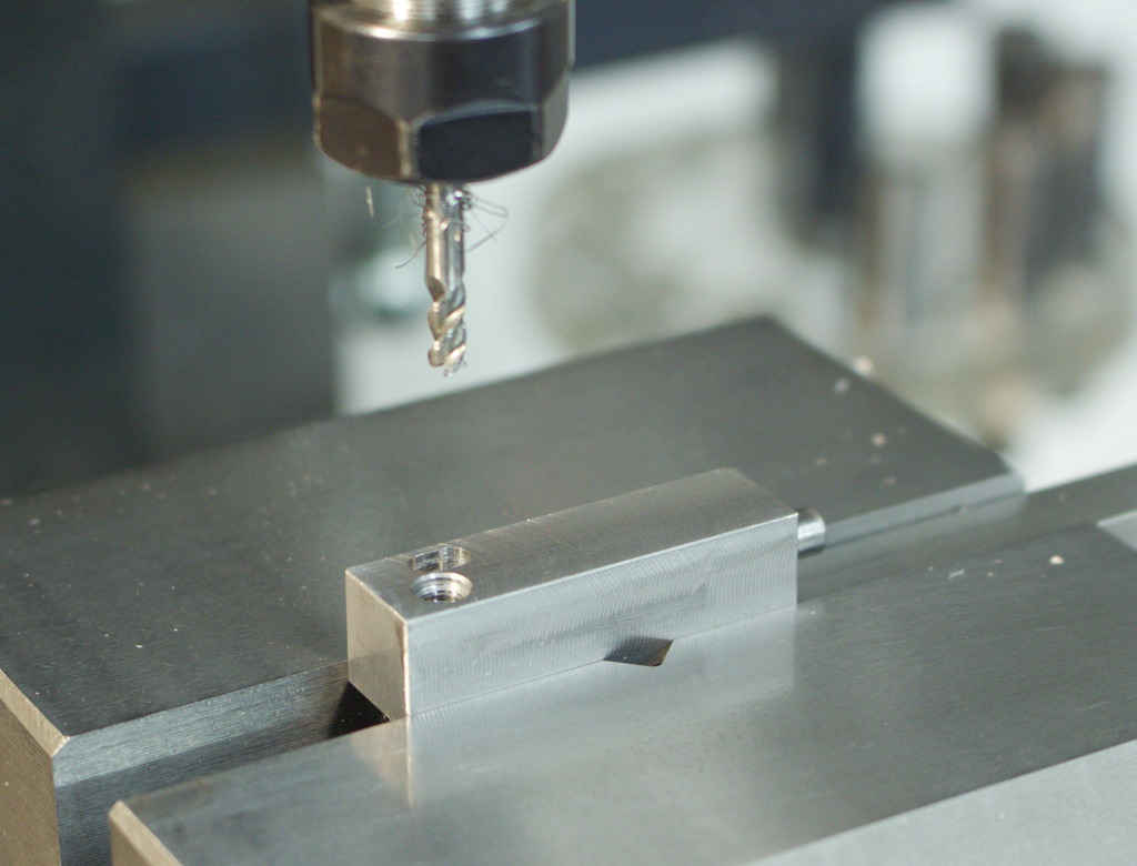
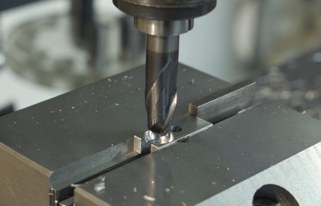
Creating a flat spot with an endmill before drilling trough:

Using a fixed boring bar to true up the bore before reaming. This ensures that the hole will be straight and on position after reaming.
Reamed to 12mm:
The larger clamping element was predrilled with a 15mm annular cutter to remove most of the material. As the cutter could not go deep enough, I flipped the parts around and drilled from two sides.
Then I trued it up with the boring bar and reamed it to 16mm.

Slitting the clamps and removing the excess material using the bandsaw and cleaning the parts up on the bandsaw:

The clamps go together like this with a central locking screw:
After hardening and quenching I beadblasted the parts with 50µ aluminium oxide and tempered them in the oven down to a hardness of 45...50Hrc.

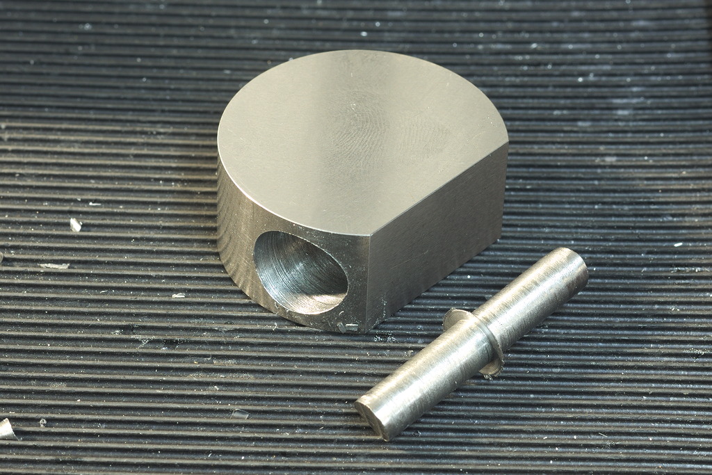
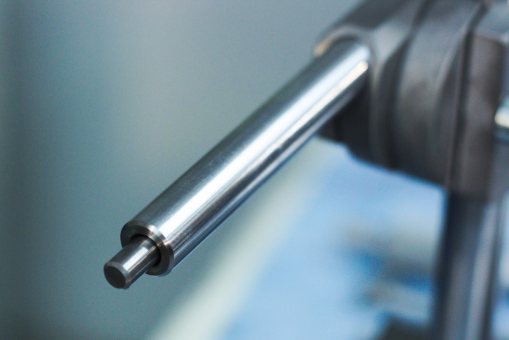
I drilled and reamed the end of the 12mm rods to a diameter of 6mm and glued in 6mm carbide round stock with Loctite 648.
This forms the connection to the balljoint and is absolutely wear resistant (and very stiff).

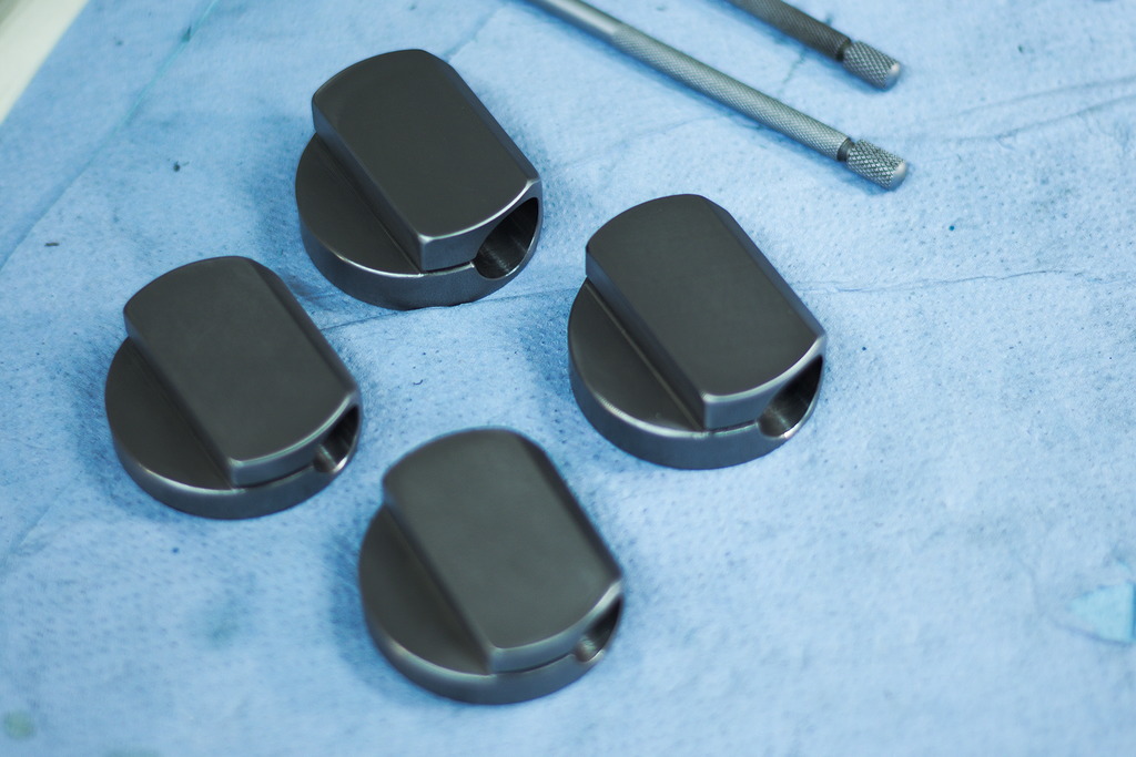
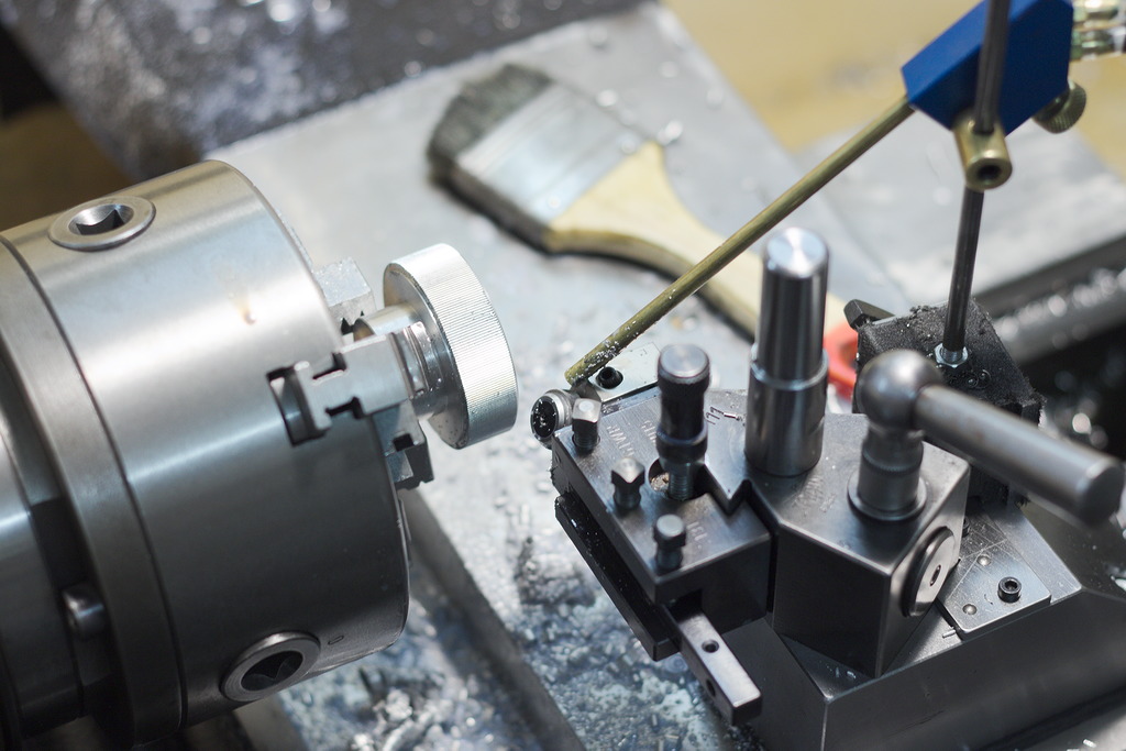
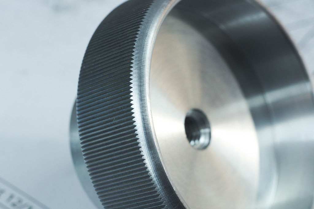
The clamping and adjustment nuts are machined from free cutting aluminium (AlCuMgPb), for the knurling I choose a straight knurl, done with a Zeus cut knurl tool.
The cut knurl tool works very well with soft materials, the fogbuster set do deliver a heavy cooleant spray works well to clear the chips.
I am very specific about my knurling, I want it completely formed out, crisp and clean:

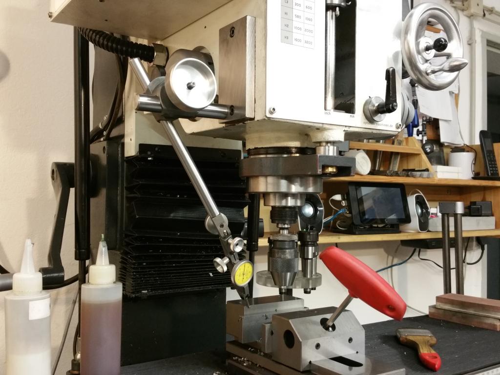
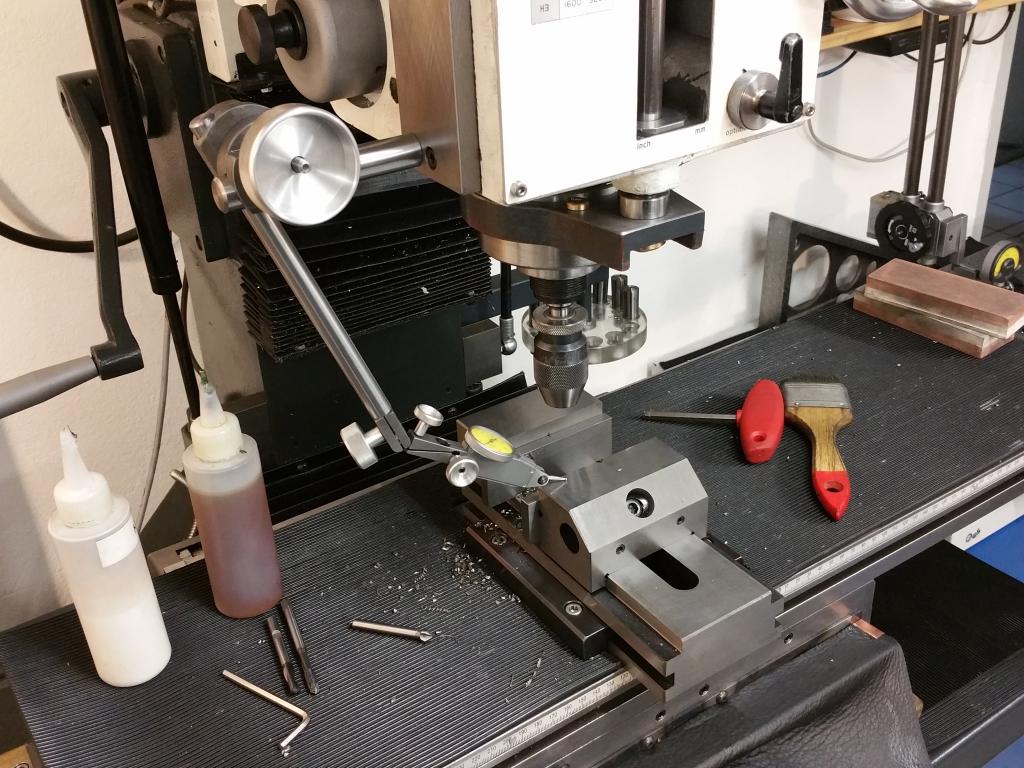
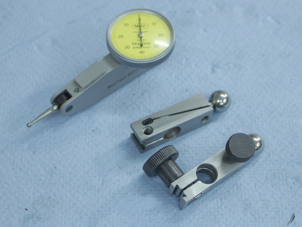
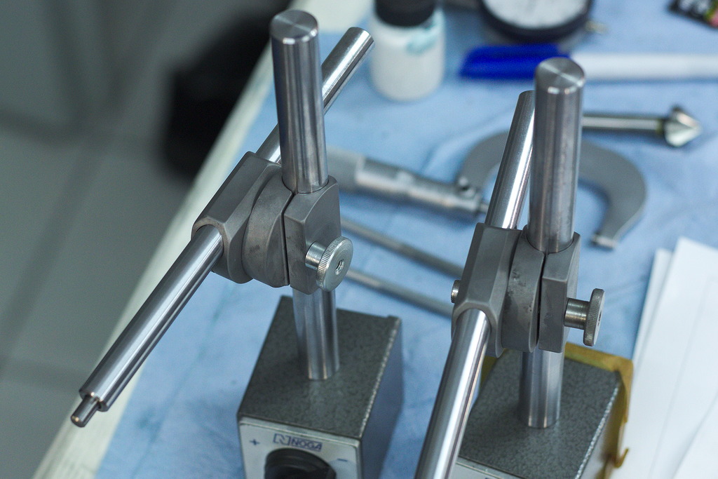
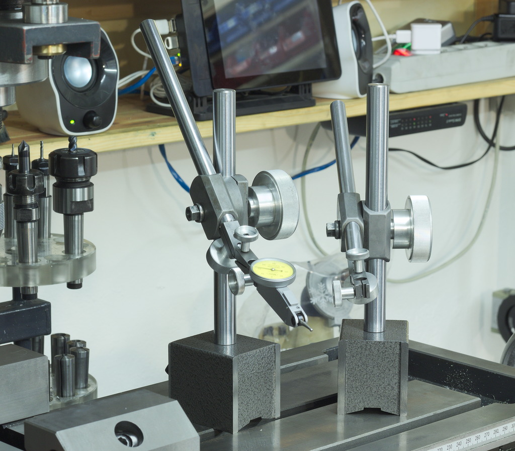
The finished indicator stands – They feel way more solid and rigid than all those with the articulating arms that I used before, the fine adjustment works well, without any slop or backlash.
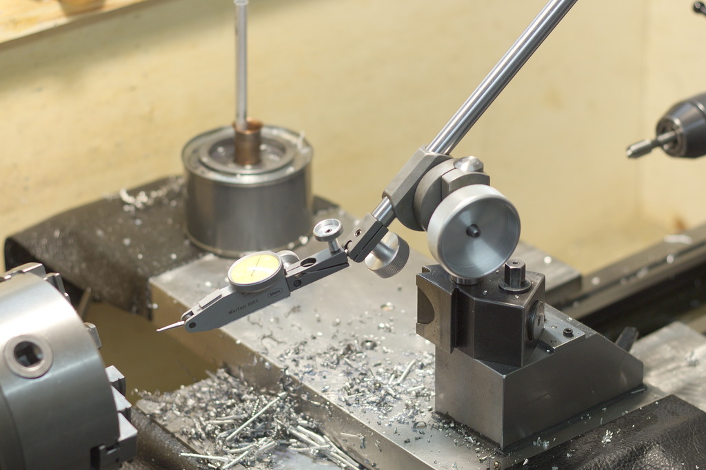
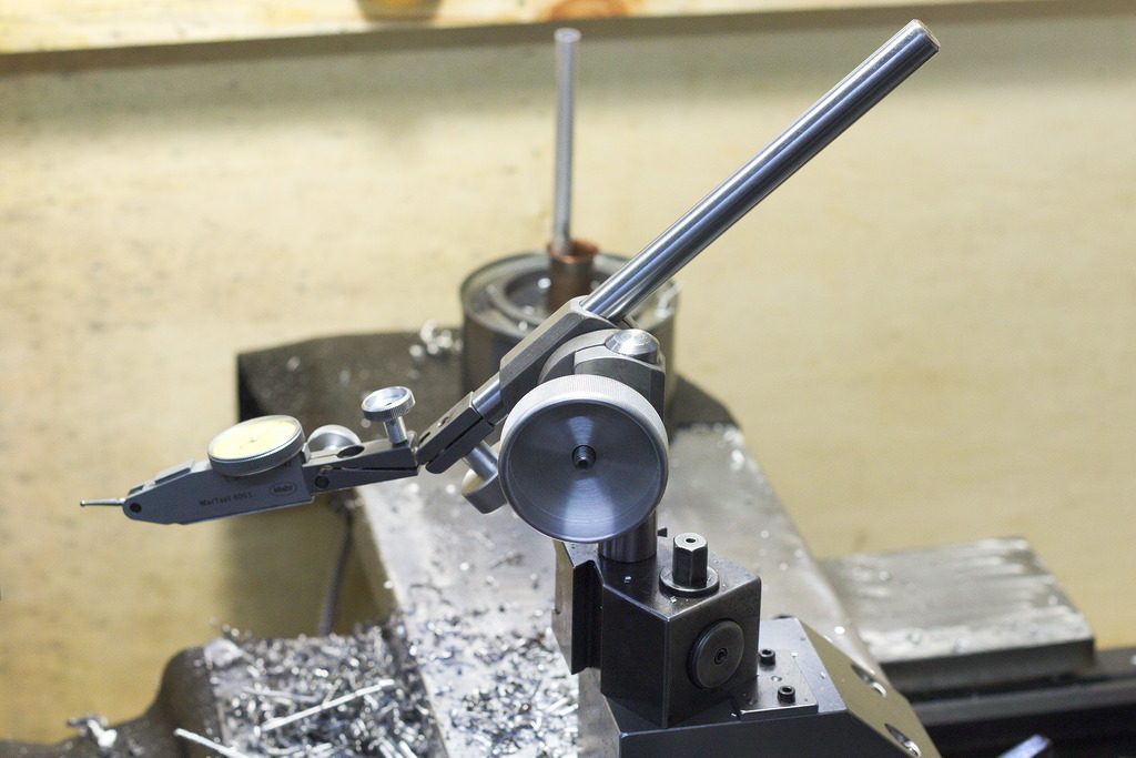
The indicator stand fits also the large cylindrical ended nut on the QCTP of my lathe – No need to find a good spot for the magnet on the cross slide of the lathe anymore:
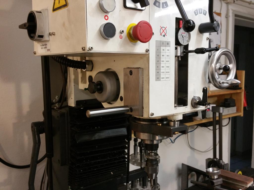
I also added a piece of 16mm shafting to the side of my mill to be able to use the indicator stand on the mill without the magnet: