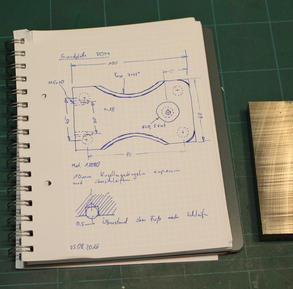
As already stated in this blogpost, I wanted to build a squareness comparator.
I started with some sketches, a piece of 1.2080 toolsteel and a piece of hardened and ground linear shaft:
I did the toolsteel not use because I need its special properties but because it was a nice ground piece the right size.
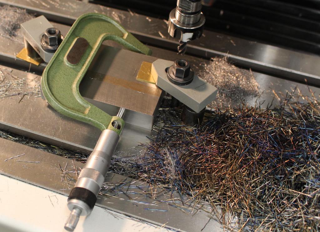
I started to machine the material for the base to size using a carbide HPC roughing endmill with non-serated flutes, which I run at 1000rpm, full thickness of the part (18mm) and about 1mm of side engagement:
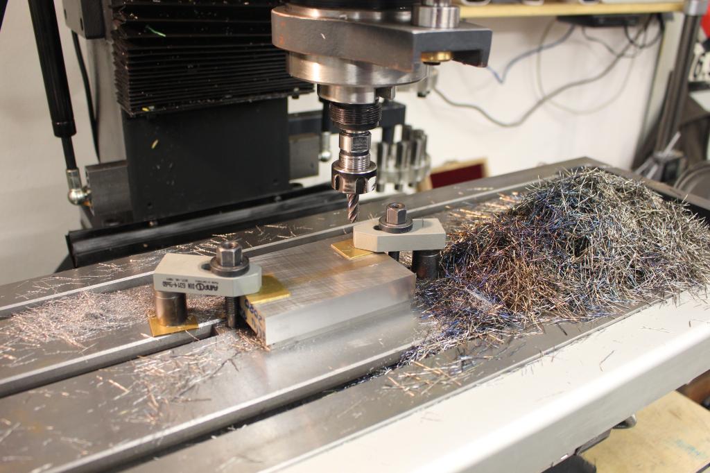
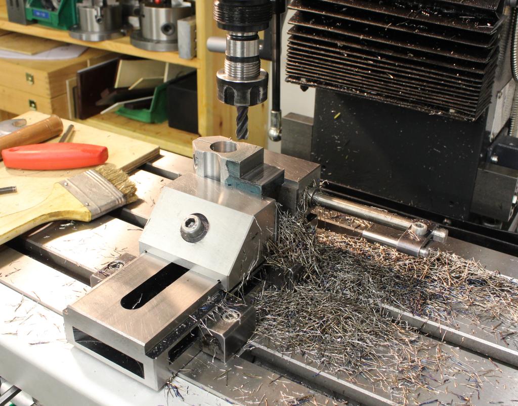
The nice thing about dry machining is the cleanup - Just by using handbroom and a shopvac I got the machine free from chips within a minute. That makes changeover between setups very simple and fast:

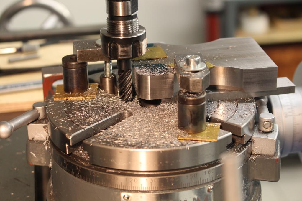
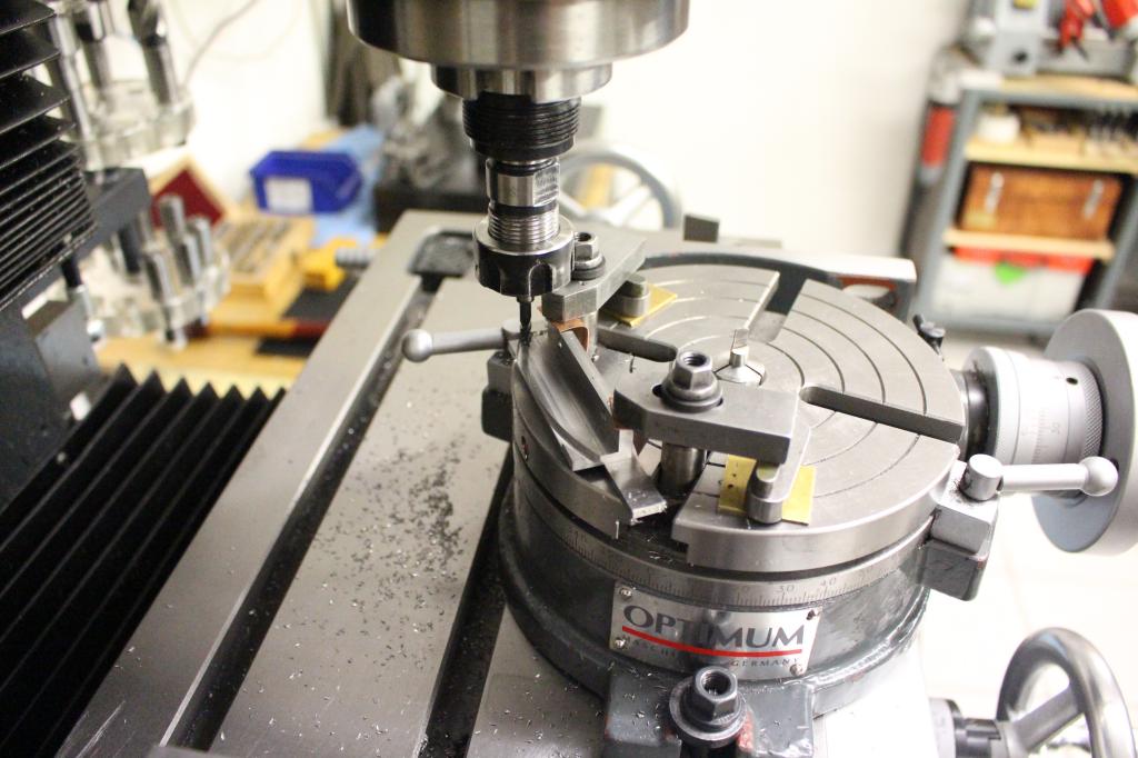
After the part was squared up I wanted to have some nice round cutouts on the side of the base. To align the part on the rotary table I use a 6mm HSS blank thats ground to half its thickness and a gage block stack to get the right distance between the part and the center of the rotary table.
To align the part in the other direction I use the square against a layout line on the part and the HSS blank:


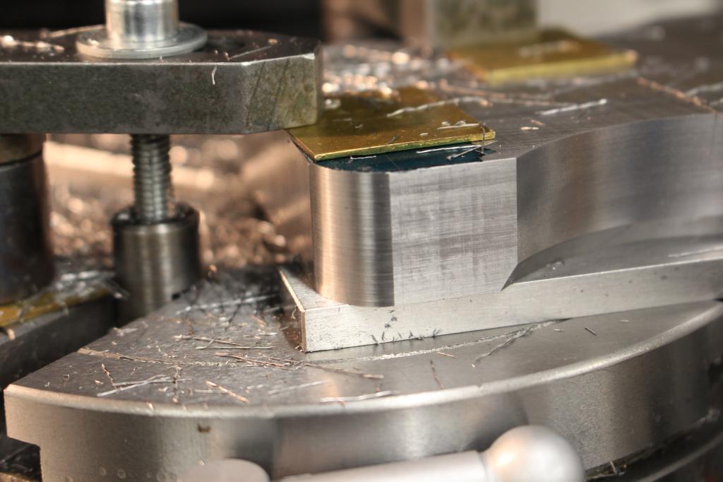
Cutting the radius:


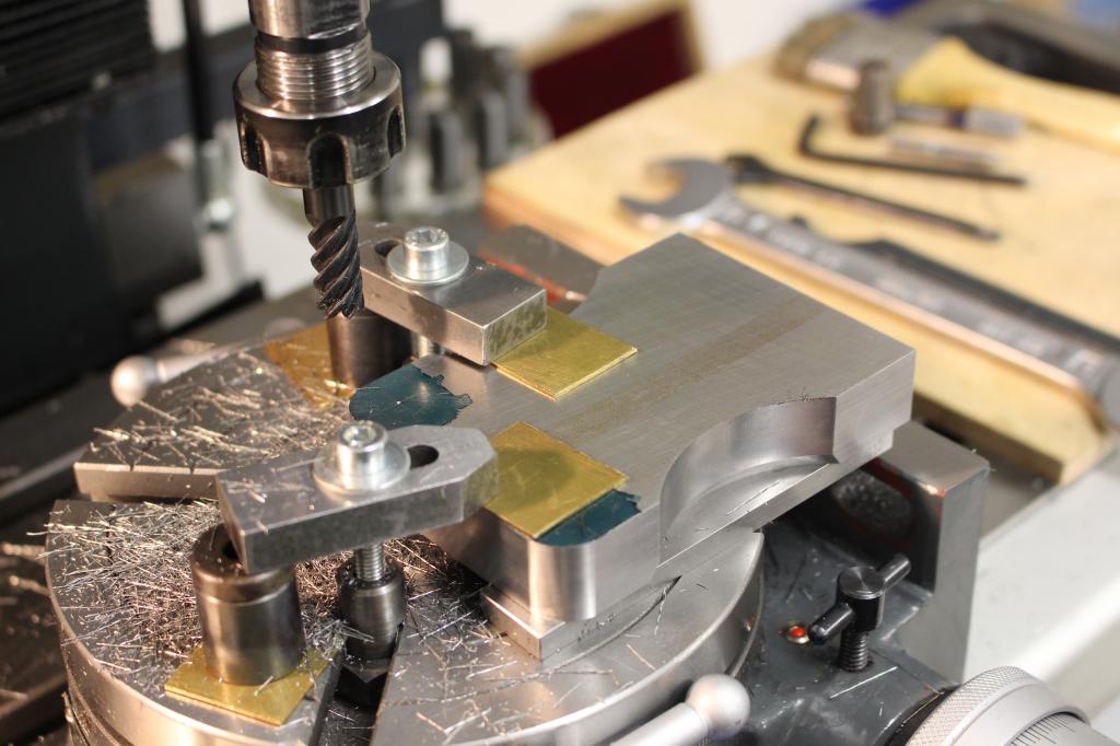
Thats the carbide endmill I used for all this milling operations. I think I had this for over half a year in use and it is still rather sharp. I use it only for side milling with large depth of cut but little side engagement.
That way you get very much life out of an endmill, opposed to using it only with a shallow depth of cut and dulling the end of the cutter instead of using the whole length of it:

Chamfering the top edge with a 60° single lip cutter:

Rounding over the rear two corners of the base. I use some layout lines to align the part on the rotary table with a center in the spindle of the milling machine:

With cutting such radii that have only cosmetic function I stay away about 0,1mm from the perfect tangent - That way I don't run into danger of cutting into the straight sides which looks quite awfull:
Borrowing the idea from Tom Lipton, I bored a few holes into the base and pressed in some ball bearing balls that I ground flat.
That way I got nice, hardened and wear resistant feet:


I am of course aware that three feet would be better, but I went for four on a purpose:
With the quite compact base I was worried that it might get tippy with three feet.
And with surface grinding the four feet I still got it to sit dead flat on my surface plate.
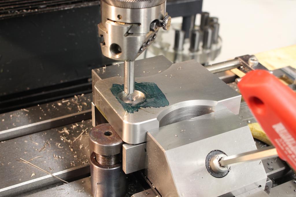
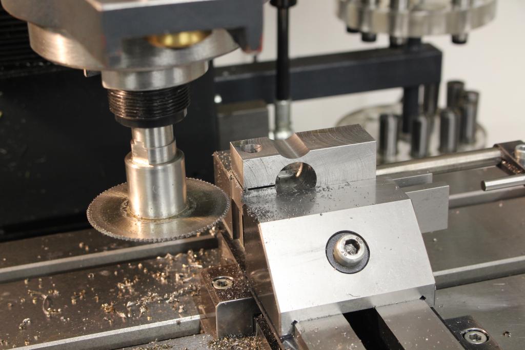
Cutting a recess for the column:

The fixed part of the indicator holder is machined out of a piece of 1.2312 - A prehardened toolsteel that machines very nice:


The indicator holder will sit about here:
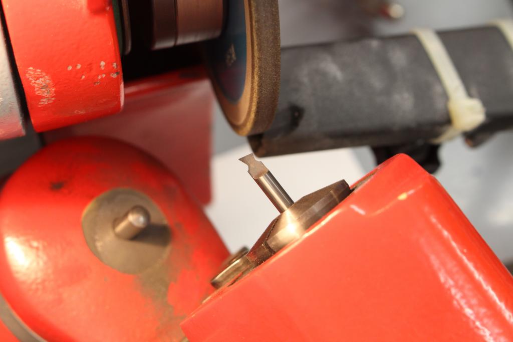
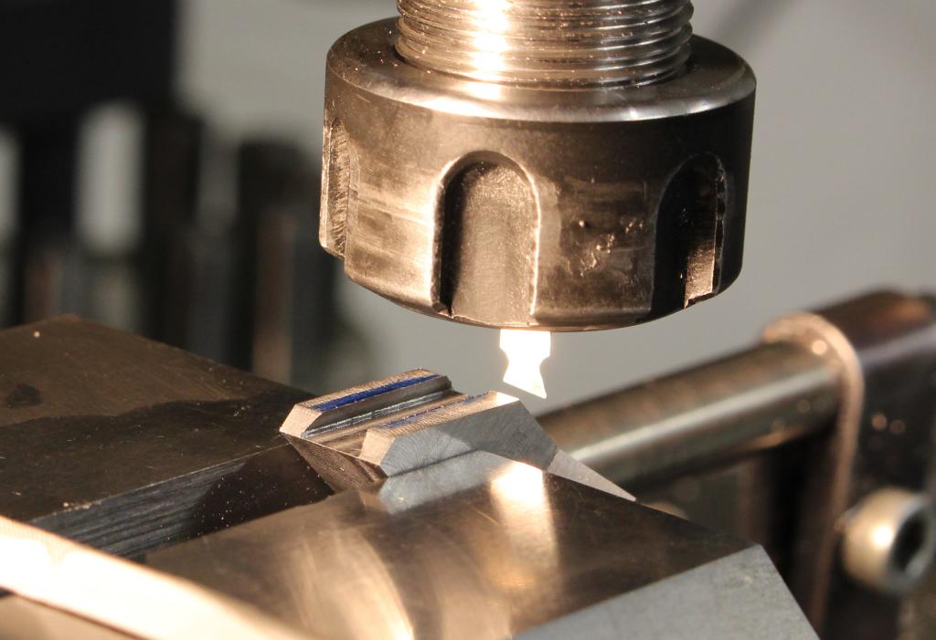
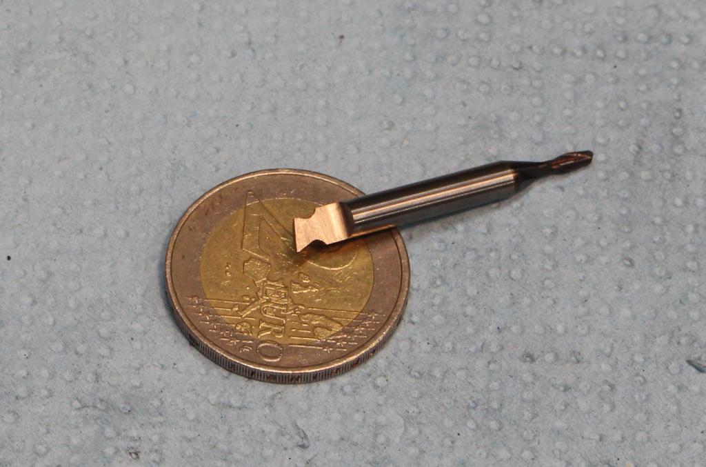
I needed a small dovetail cutter for the indicator holder. I ground it on the single lip cutter grinder out of an broken carbide endmill - It performed very well:
The fixed and adjusting indicator holder are held together by a piece of spring steel which acts as a hinge.
The hardened springsteel is quite tough but you can machine it with HSS endmills and drills if you keep the speeds very low.
I prefer to mill it with carbide endmills and drill it with carbide ball endmills:

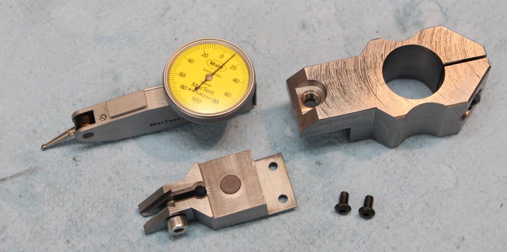
The complete indicator holder put together:


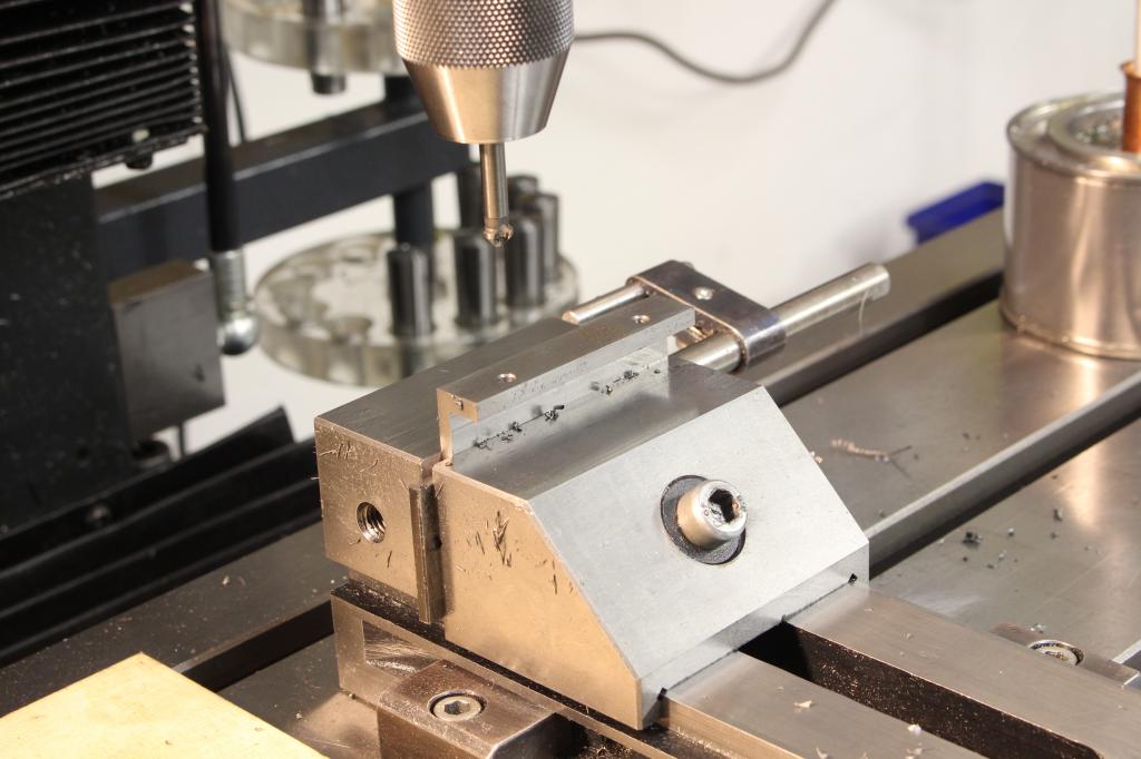
In the spot where the adjustment screw will hit I drilled a hole where I pressed in another bearing ball, that got ground flat. This gives a nice hardened surface for the screw to act on:

It is starting to take shape:
The bumper with the large radius got machined out of another piece of 1.2080 toolsteel:

The L-shape was roughed out with some allowance for grinding:

Machining the big radius on front of the bumper:

I hardened the part with the oxy/fuel torch and tempered it to be about 50-55HRC - Checked with the hardness testing files:

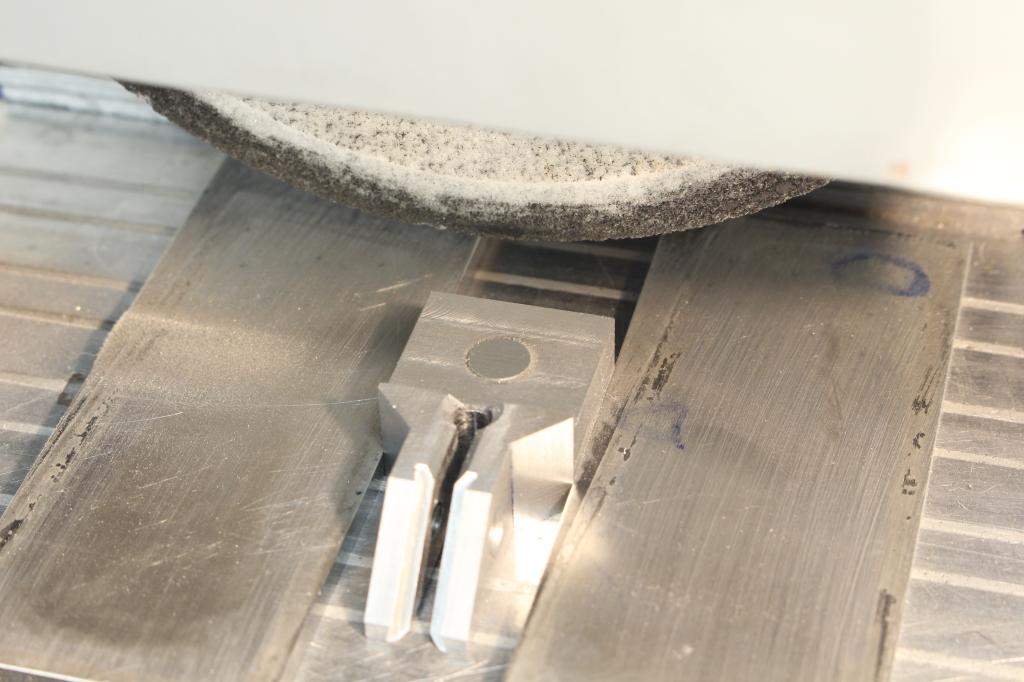
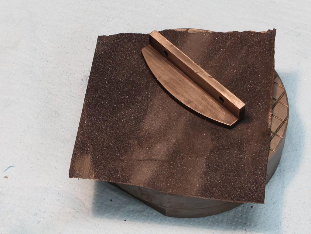
Removing the scaling on a piece of 280grit sanding paper, as it tends to gum up the grinding wheel:
The part got ground all over, with exception of the radius, as I don't have a spin fixture for my grinder:

I cleaned up the radius by hard milling with carbide tooling. A chamfer got added too.
Hard milling is nothing to be in fear of - Just use good carbide tooling, rather high speeds and shallow cuts. Again, I prefer to take a big DOC and only very little side engagement:

Final cleanup on the radius with a stone, removing all the remaining toolmarks:

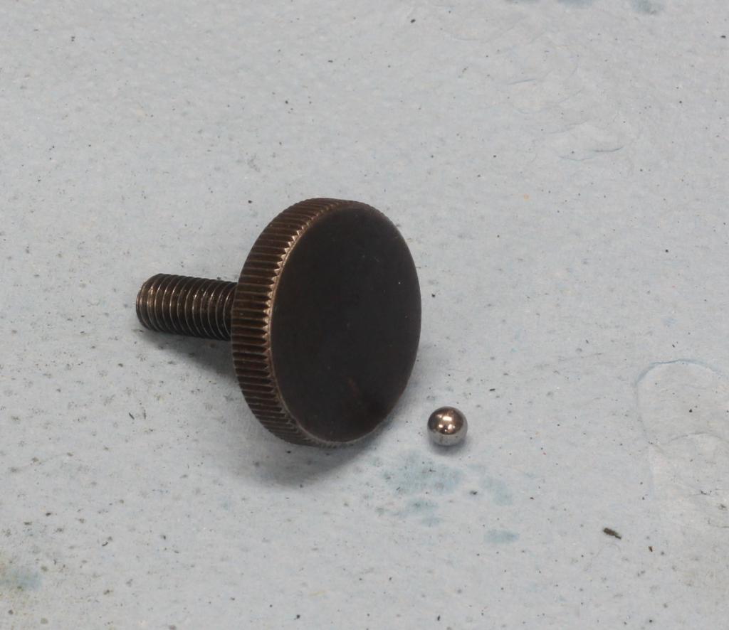
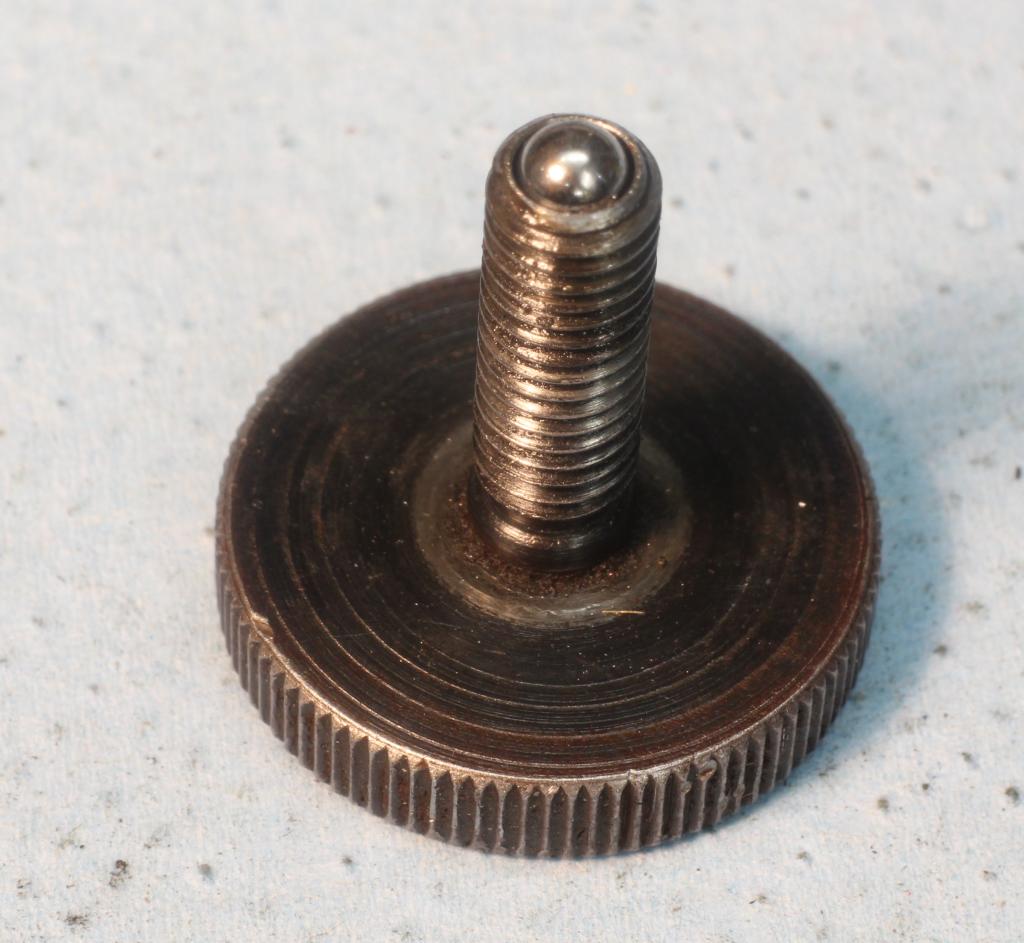
For the adjustmentscrew I used a knurled screw out of my screw collection. I drilled out the end and pressed in a 4mm bearing ball. That way I get a hardened point to surface contact which results in a very smooth action:
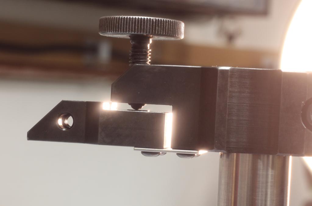
Here is a side view trough the fine adjustment - You can see the screw with the ball-tip acting against the hardened pad in the indicator holder. Below it sits the spring steel hinge:
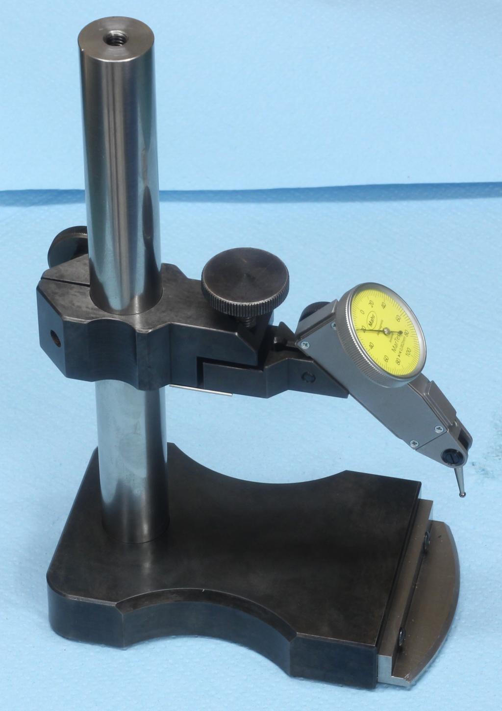
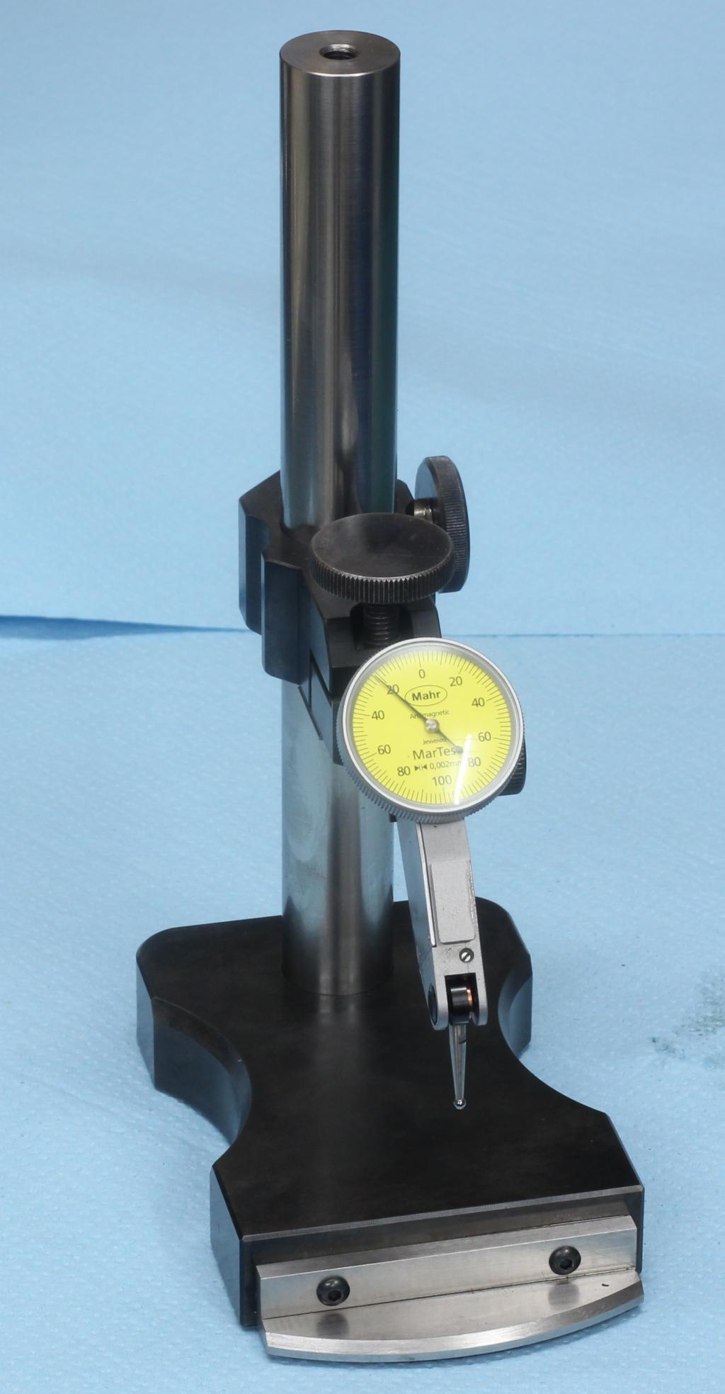
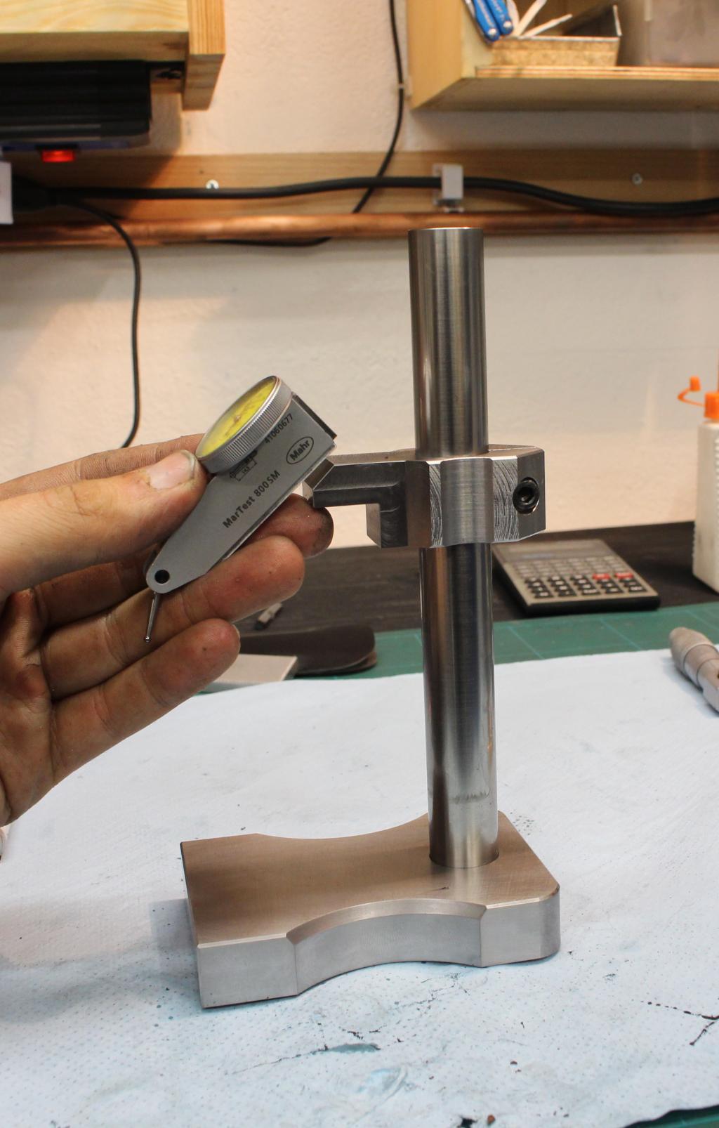
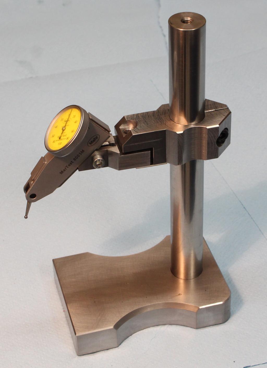
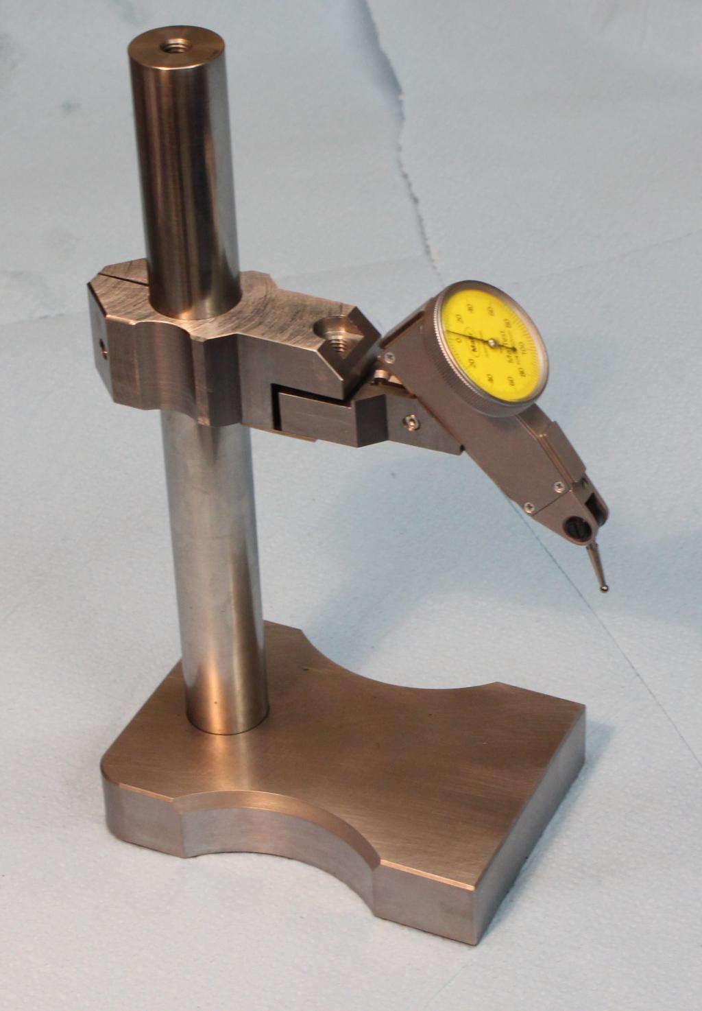
The finished squareness comparator: