That way, if you had an additional rotary axis, you could easily grind concave faces for broaches.
This will be a collection of some simple tips and techniques that I have learned from others or by myself over the years and use regularly.
Grinding carbide on the milling machine - 07-11-2017
Dress resin bound diamond wheels - 07-11-2017
Grind multi purpose lathe tools - 07-11-2017
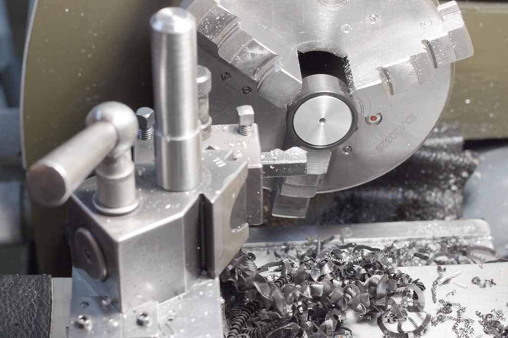
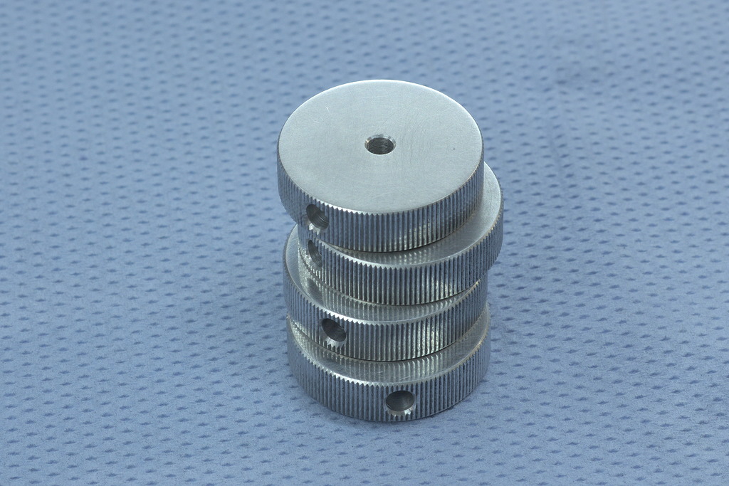
Holding delicate, knurled parts in the three jaw chuck - 07-11-2017
Quick way to make a radius grooving tool - 27-03-2017
Grinding external radius lathe tools - 20-03-2017
Regrinding carbide inserts for special operations - 03-02-2017
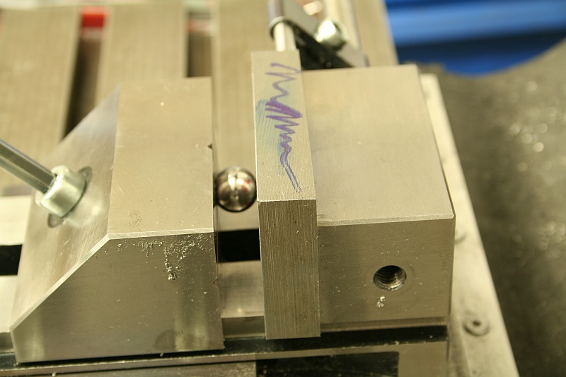
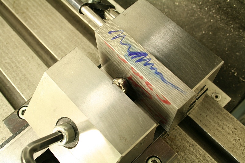
Using a ball bearing to hold rough and non parallel parts in a vice - 03-02-2017
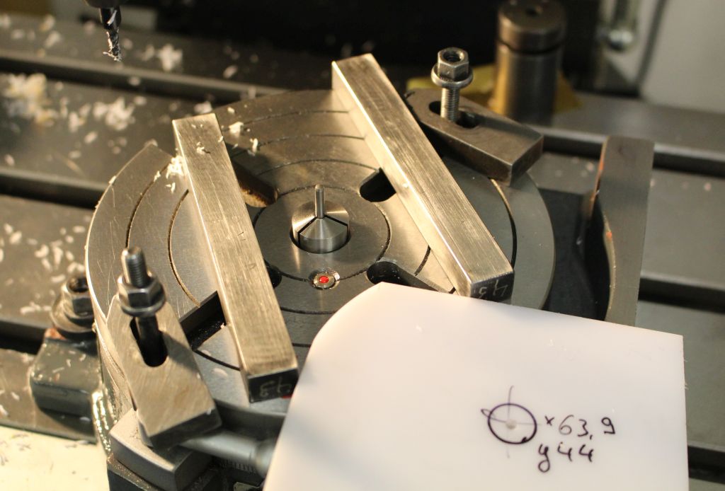
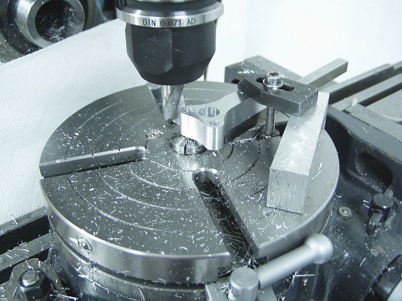
Centering work on the rotary table - 03-02-2017
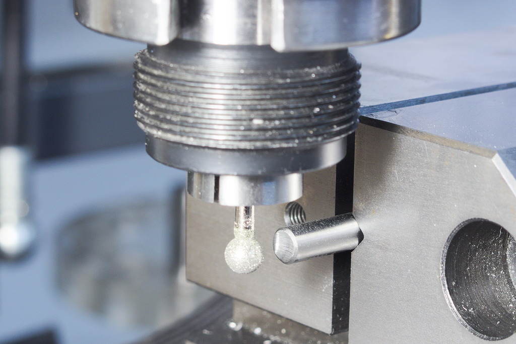
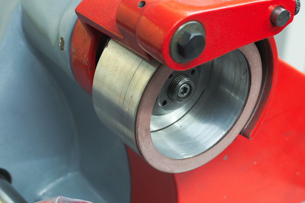
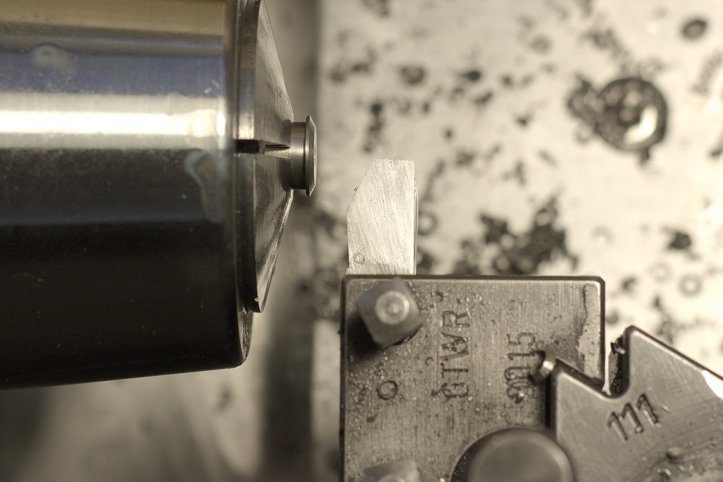
I wanted to try that myself, using very cheap diamond grinding tools, like you would use in a die grinder, in the milling machine. Spindle speed was 2000rpm and I fed the carbide blank (broken endmill..) sideways into the ballshaped diamond tool. It works suprisingly well, the diamond cuts very free, progress is relatively fast.
That way, if you had an additional rotary axis, you could easily grind concave faces for broaches.
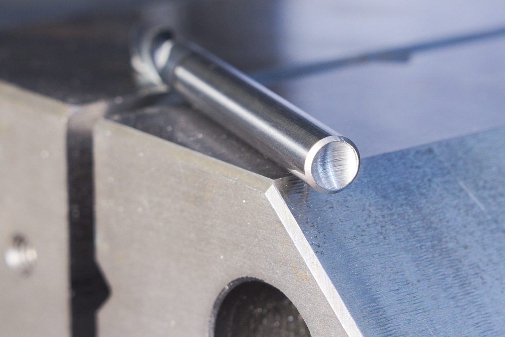
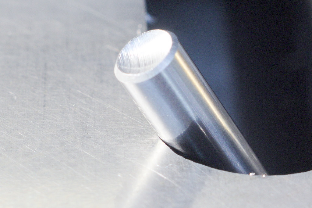
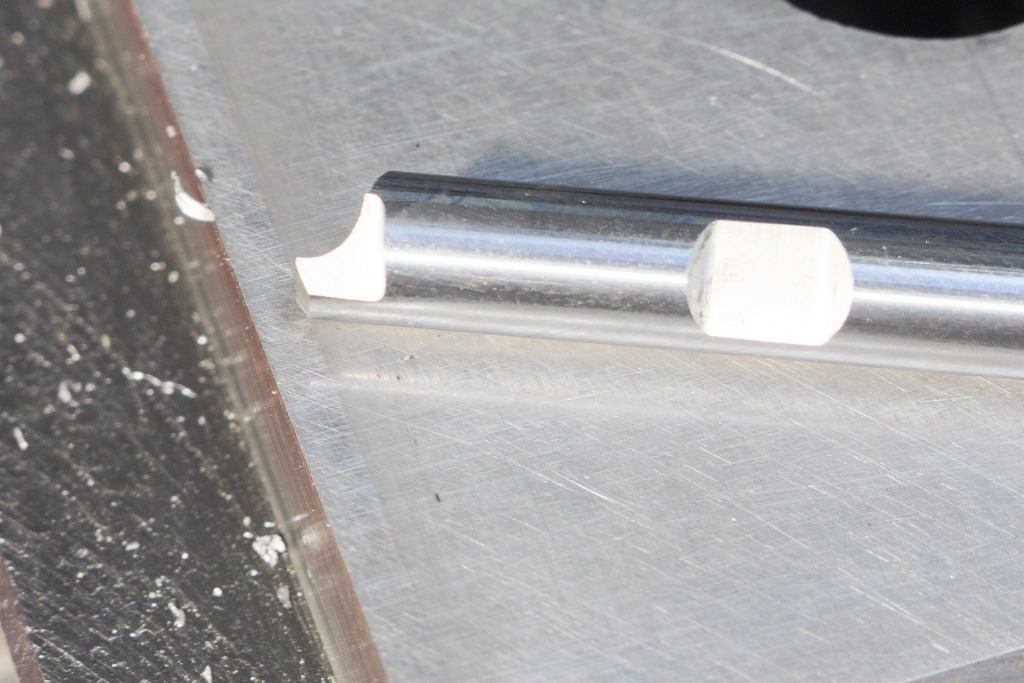
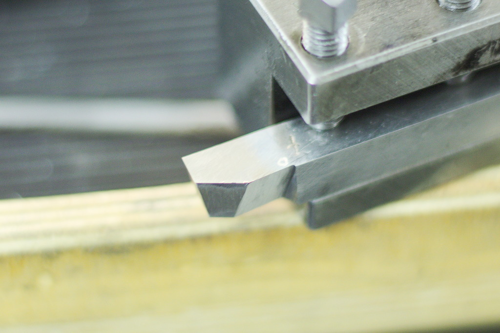
With a conical tool, you can grind very nice radius tools for the lathe - Size of the radius is controlled by the depth of the tool in the work and the conical shape creates the clearance angle automaticaly. As it is a round piece of carbide in this case, I ground the other side flat after forming the radius (Just freehand against a diamond wheel) and a simple radius tool was finished.
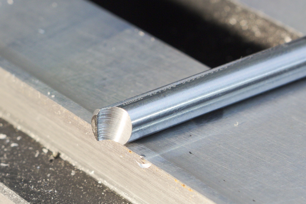
In my mind this is a great addition to the evergrowing list of small tricks to pull yourself out of a ditch, when you need a custom tool for a rush job.
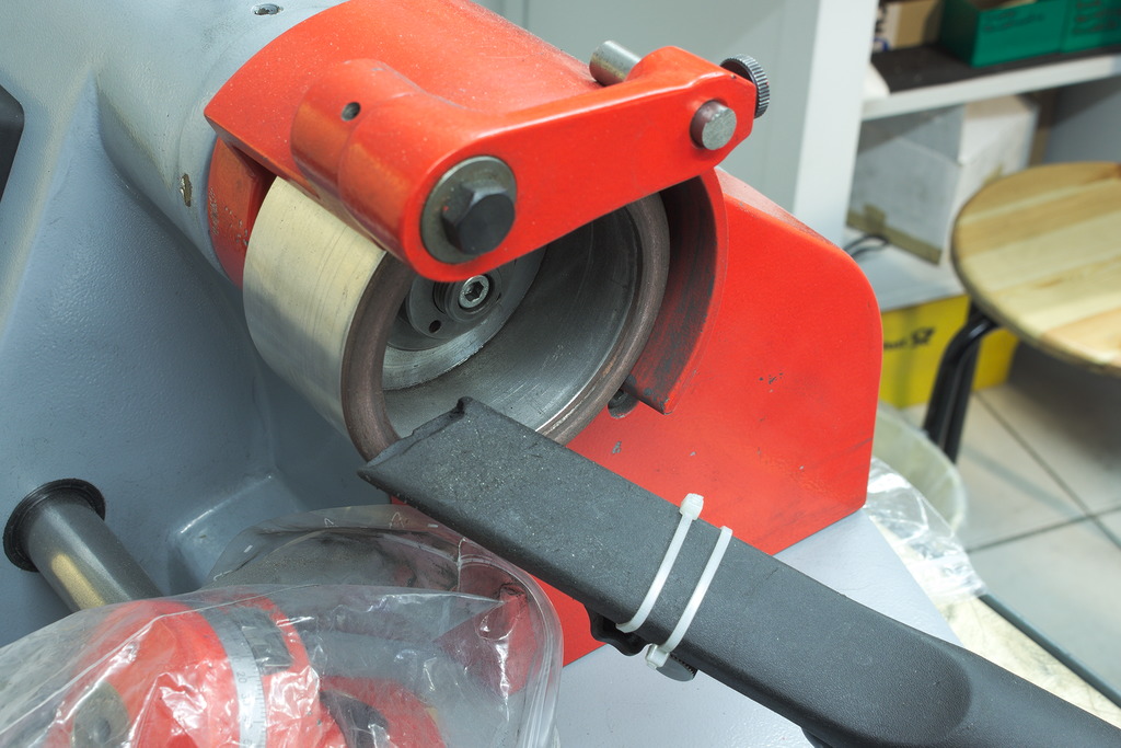
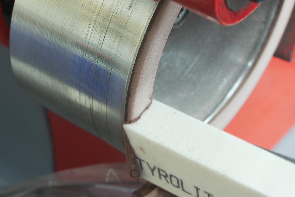
Then I went ahead and used the molybendium instead of the diamond to dress the wheel - Small depth of cut and relatively fast traverse speed less than half a second to get across the wheels face. And slowly, the wheel got back to flat.
After dressing the wheel like that, the diamond grit and the resin binder are at the same level and the wheel does not cut very well. With a sharpening stick for diamond wheels you can trim the resin back and expose the diamond:
After the dressing/sharpening process, I am left with a perfectly flat wheel again:
It is a good idea to use dust extraction, the process creates a lot of molybdenium dust, that you better not breathe.
The first one is a Horn 312 parting insert, ground to do parting, facing and outside turning:
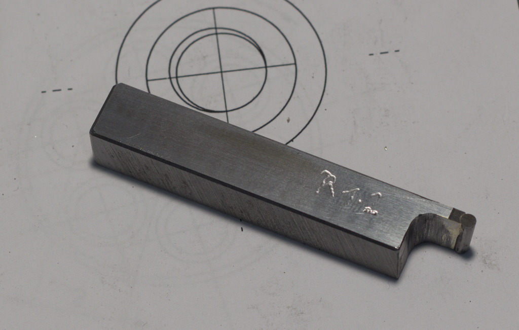
This is a Hss tool, specific ground for 27° chamfers and to face the part:

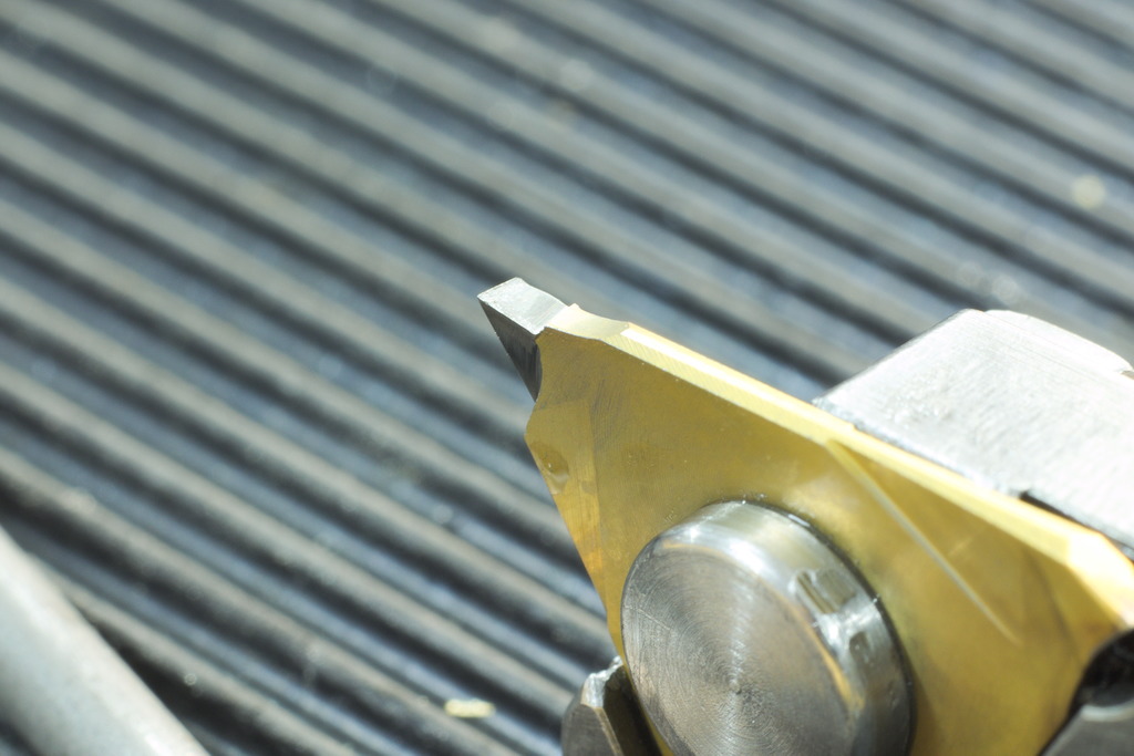
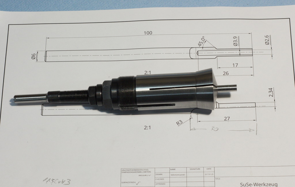
The finished toolshank with the 2,4mm Hss blank:
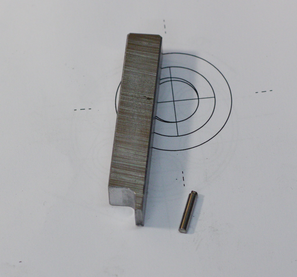
The Hss blank got hard silver soldered into the shank (Hss does not loose its hardness when silver soldered) and then ground sharp on the surface grinder (It could also done on the benchgrinder):
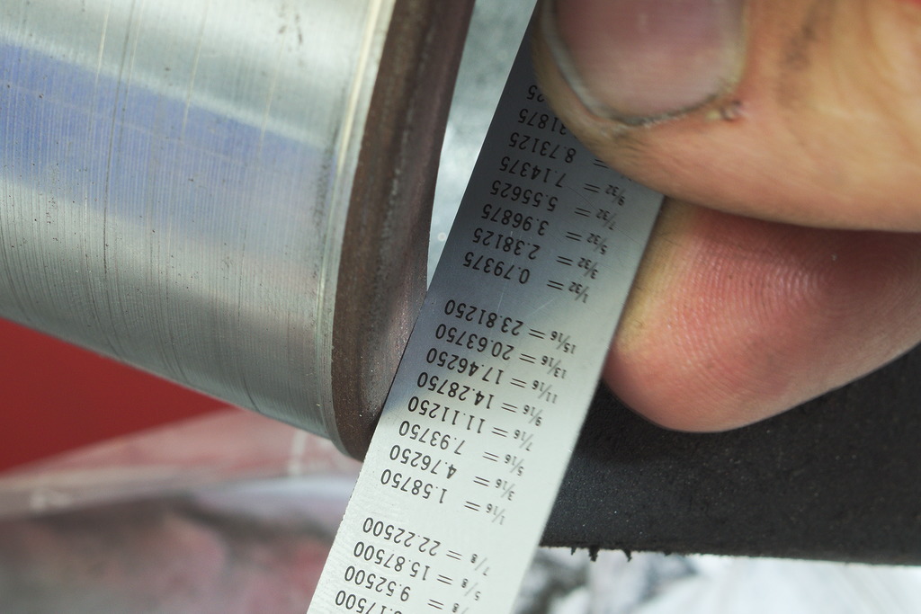
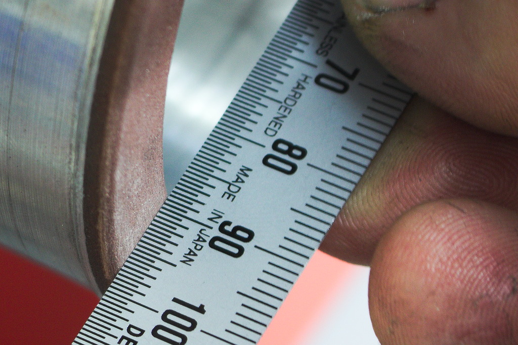
The 5° tilted round Hss blank alters the actual radius that the tool creates slightly, but in this case, the error is only 5/1000mm on the radius. It is quite easy to check this in a Cad program
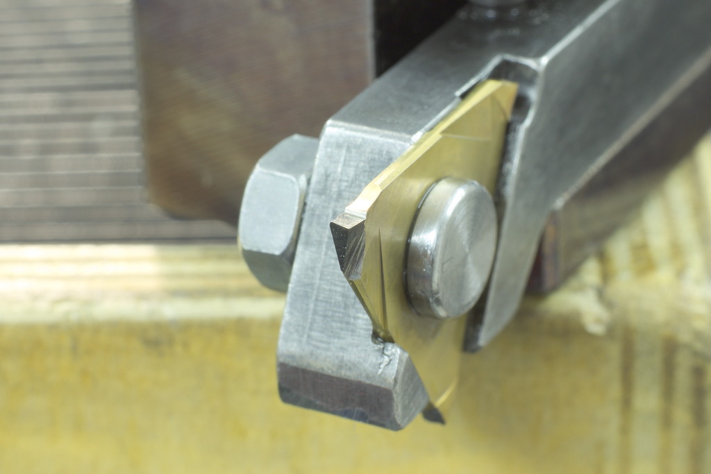
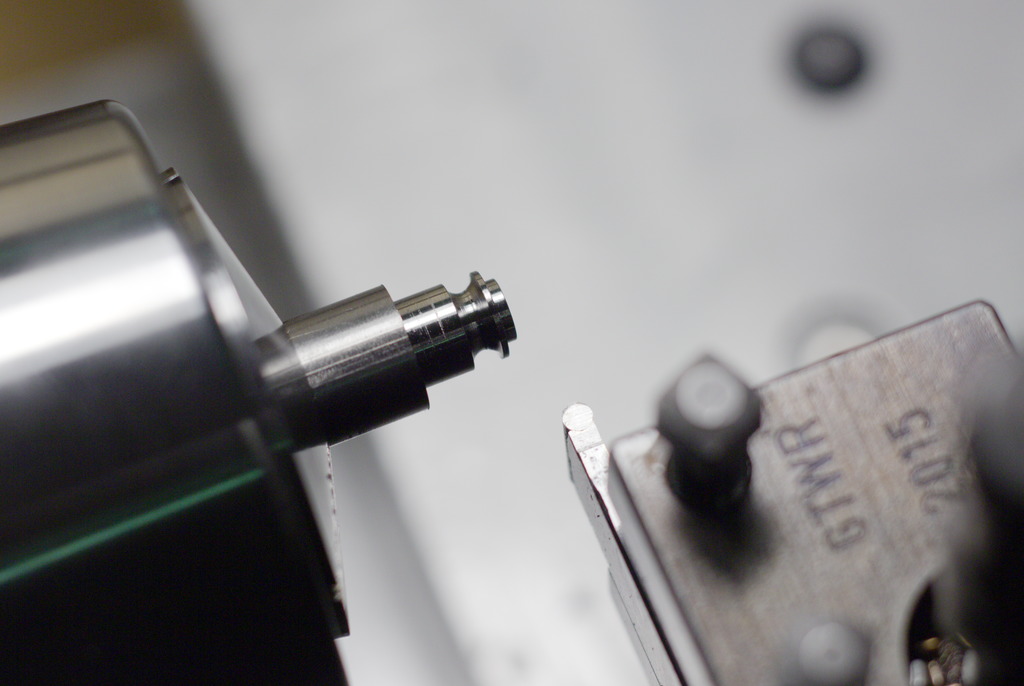
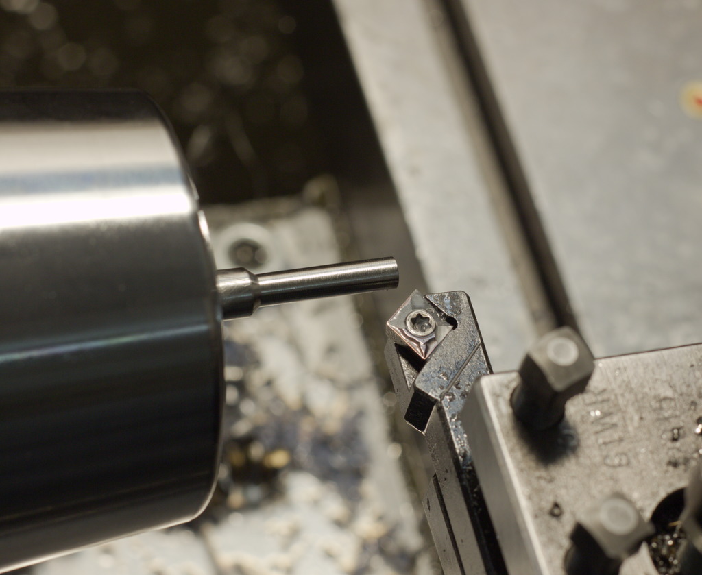
The tool in use to machine a radius groove into titanium - The tool will only plungecut but not cut to the side, as there is no clearance to the side built into it:
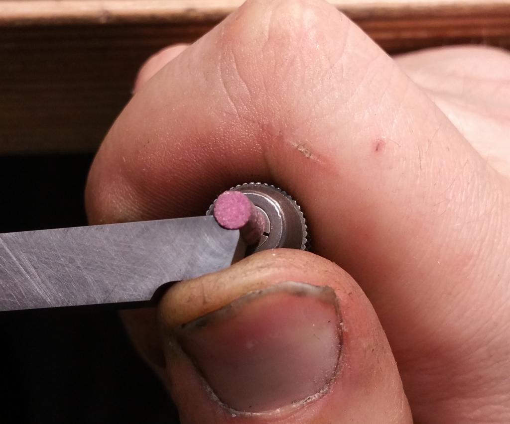
When doing this, I prefer to run the rotary tool quite slow to be able to press it tightly into the radius I want to form. Using a permanent marker on the surfaces to be ground shows you the progress.
I did also not want to come back with a second tool for finishing, as I had to make a bunch of them.
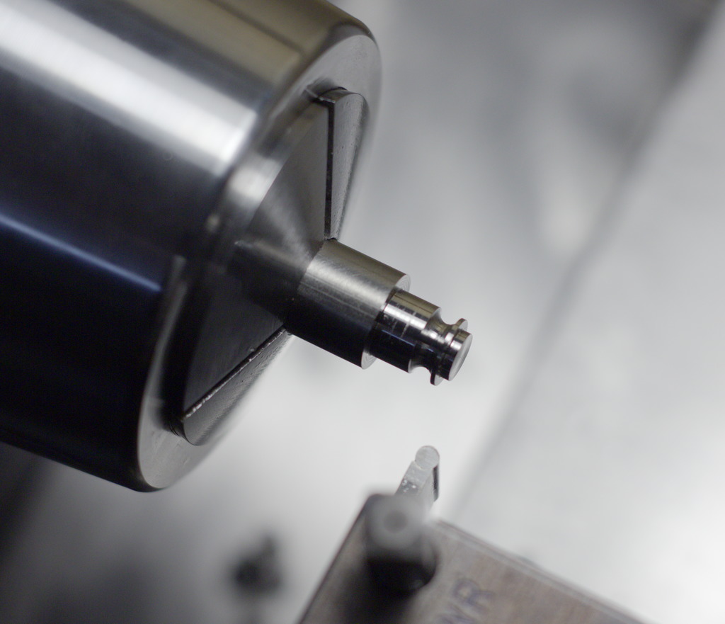
I decided that a normal CCMT06 finishing insert with a 0,2mm nose radius is a good starting point, but I ground a substancial back- and side rake to the top of the insert.
That way I was able to rough and finish with two cuts - First cut took it down to 4mm in diameter, second cut finished it to 3,9mm +-0,01mm.
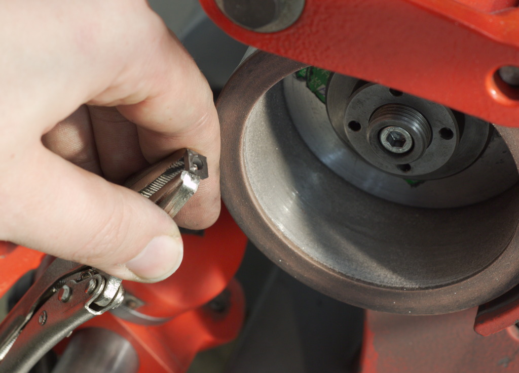
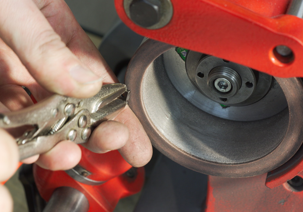
The way the insert was ground is very primitive: I grab them with a needle nose vice grip.
Then the the top face of the insert is held freehand against a diamond wheel, eyeballing the angles - I tipped the top surface about 5° back and to the right, to create a nice, positive cutting action with very little cutting pressure. As the insert has already a nose radius of 0,2mm, it is also a very durable tool.
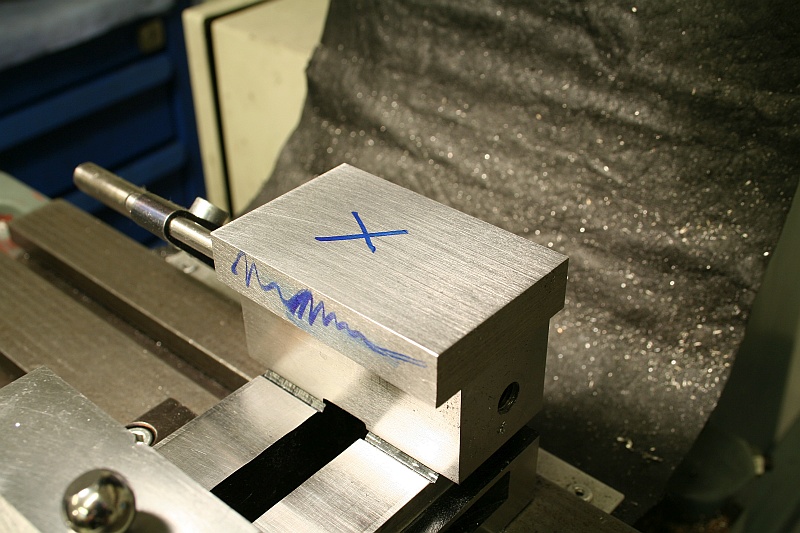
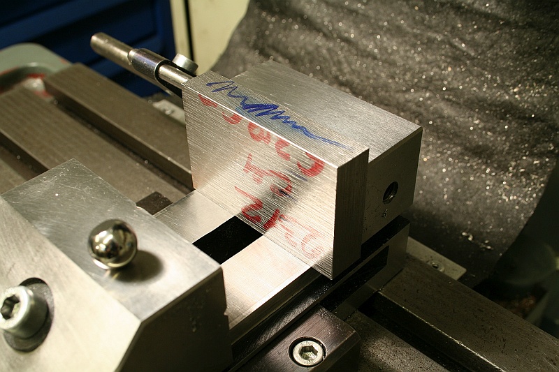
I improved the way I grind/regrind the inserts by using the surface grinder - That way, they all come out exactly the same.
The procedure is shown in this video: Regrinding carbide inserts
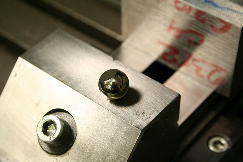
By using the bearing ball on one side, you create a pointcontact situation against the workpiece and non-parallel surfaces are not an issue anymore.