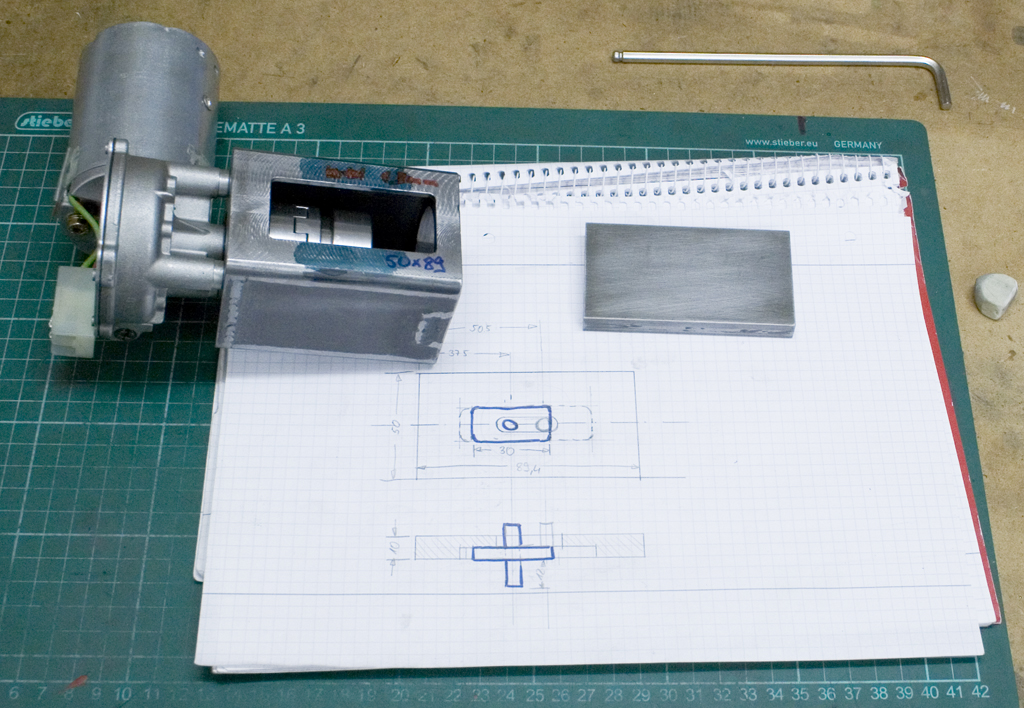
From the moment decided to buy a manual milling machine I knew that I wanted a powerfeed in at least one axis. From a friend I got a 24V geared DC motor out of some PCB manufacturing equipment that I wanted to use for this purpose.
Testing showed that the motor runs at 95rpm with a voltage of 17V (My lab powersupply cant deliver more), with the 24V it will run about 120rpm, which gives a feed of 360mm/min (Considering the 3mm pitch of the leadscrew).
Speedcontroller for the motor:
REGLER DZ :: 10-A speed controller for DC motors
Power supply:
SNT MW150-24 :: Switching power supply, closed, 24 V / 6.3 A / 150 W
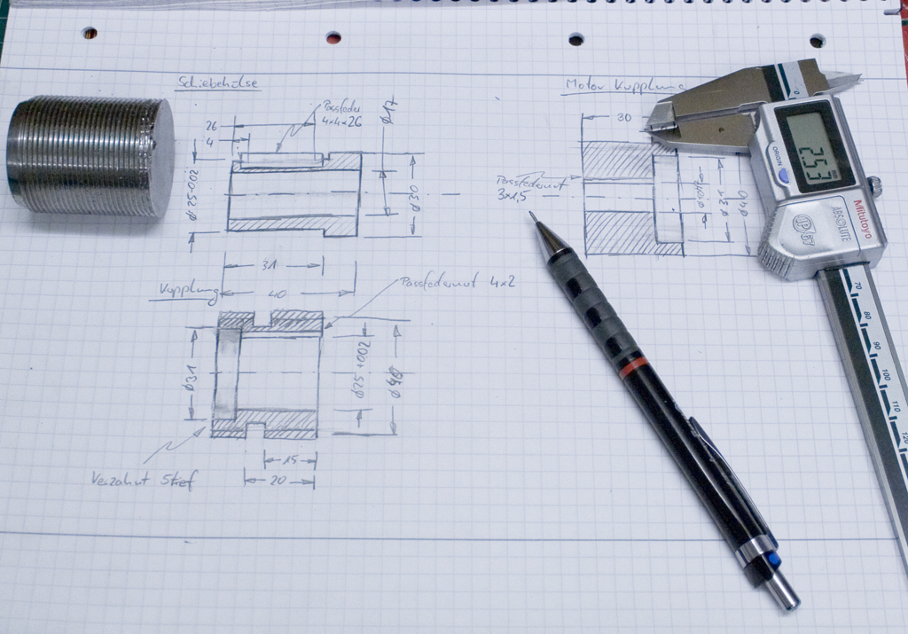
A german home shop machinist has a nice set of drawings for a smaller machine (Optimum BF20) on his website, which I wanted to use in a slightly modified version.
There is a four part video series on building the powerfeed:
Part 1 - Youtube
Part 2 - Youtube
Part 3 - Youtube
Part 4 - Youtube
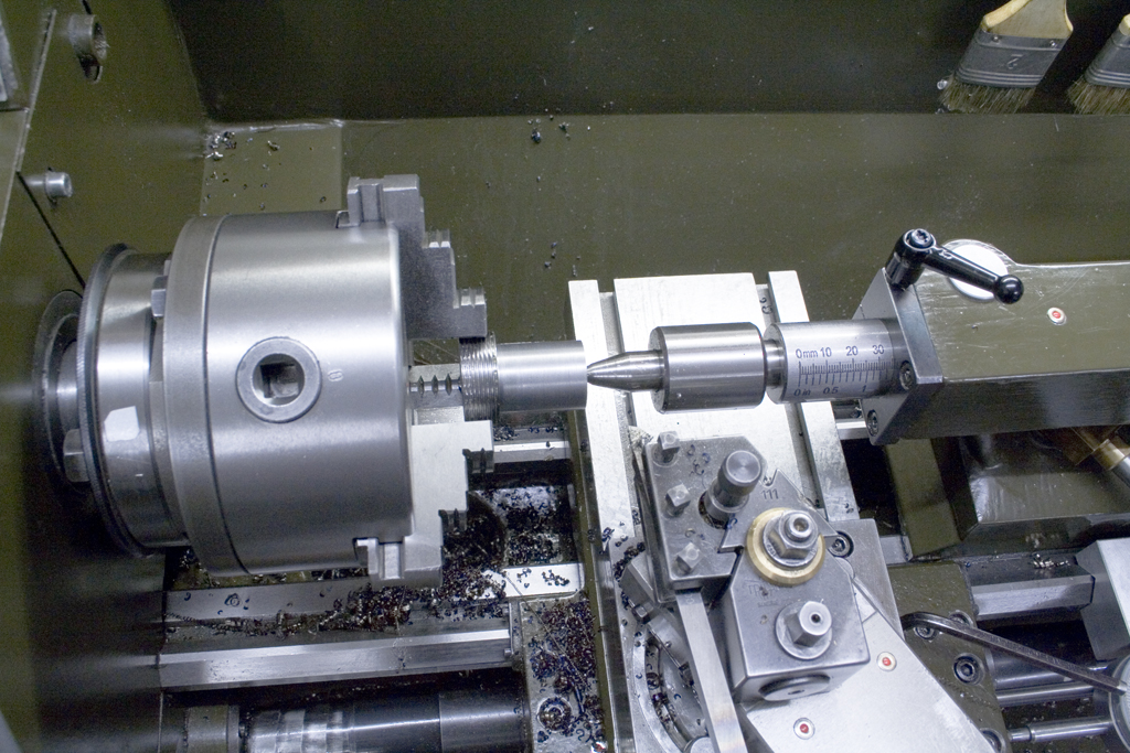
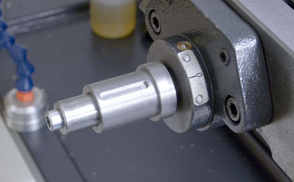
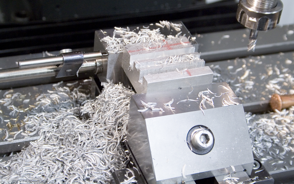
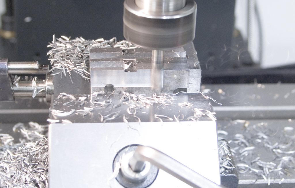
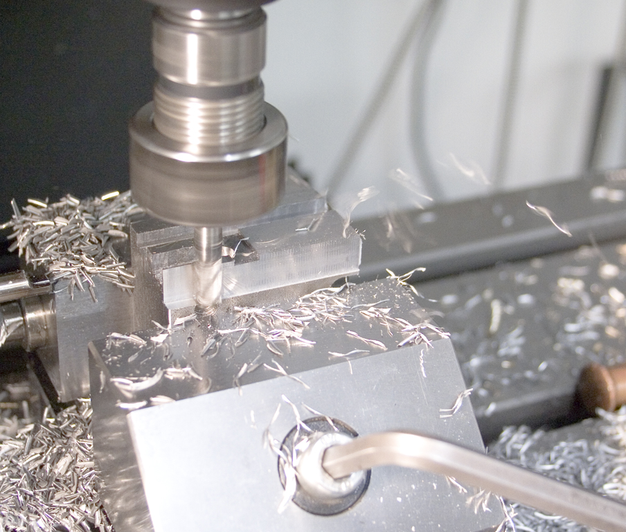
Machining the adapter for the sliding coupling that mounts on the feed screw:
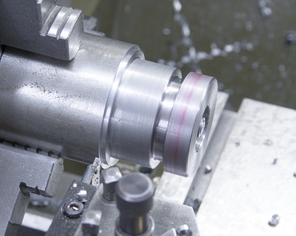
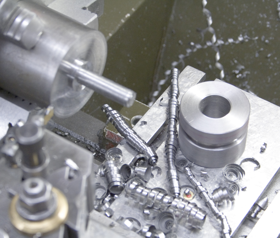
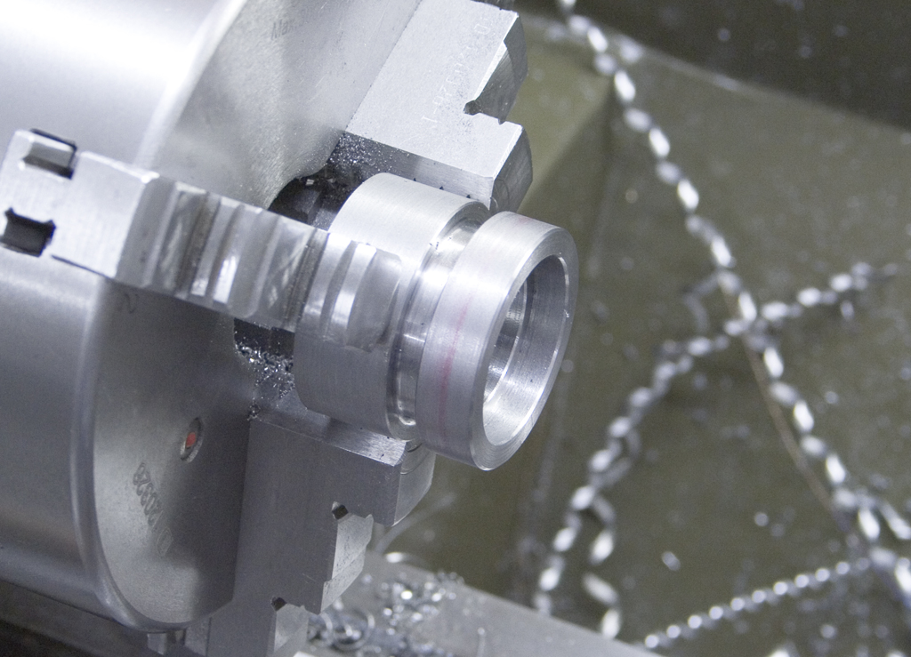
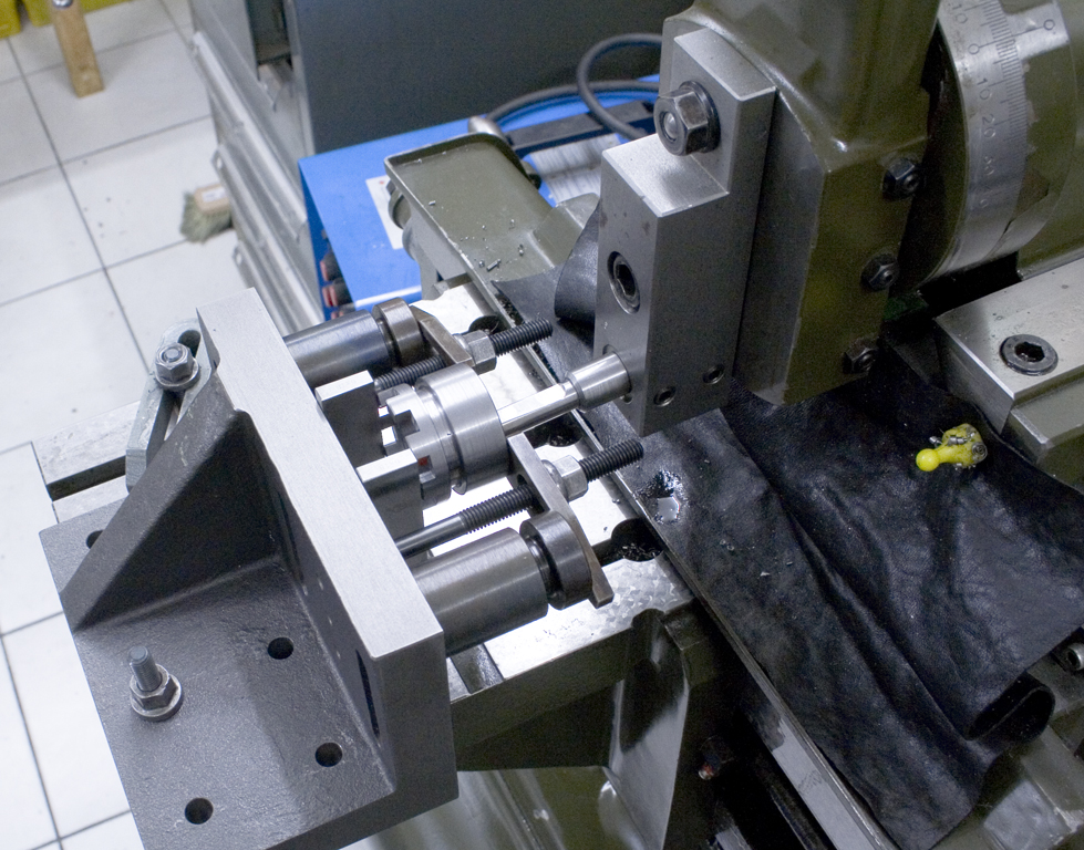
Turning the clutch parts:
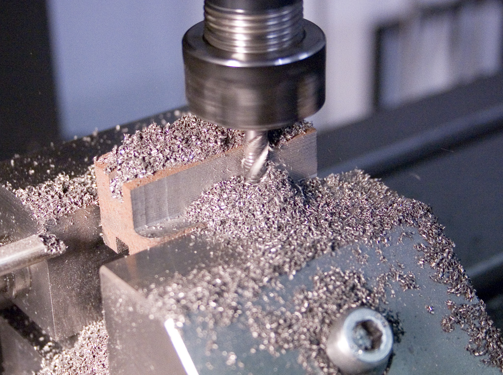
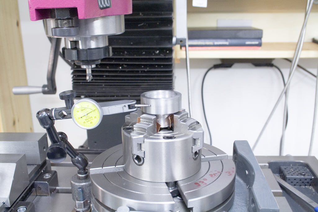
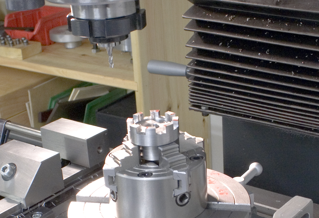
Machining the clutch teeth on the rotary table:
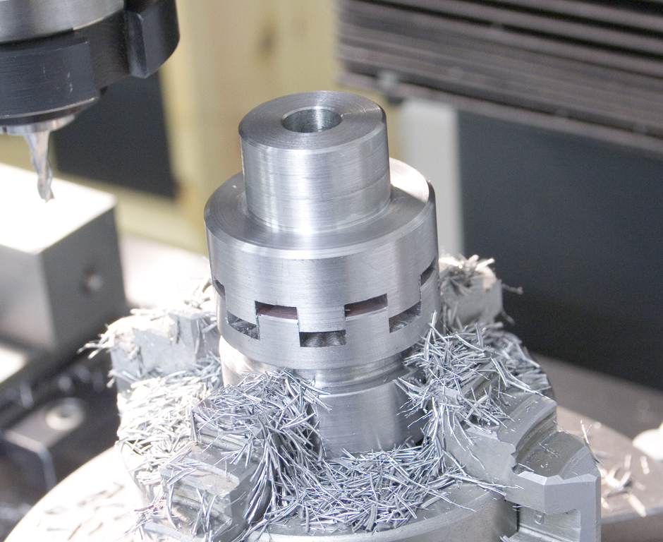
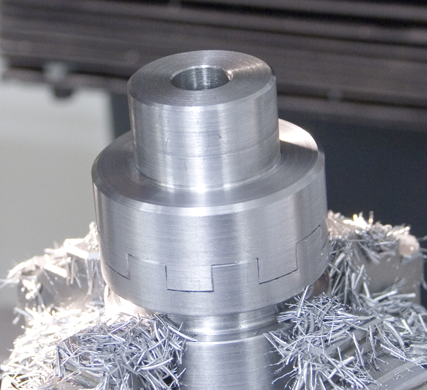
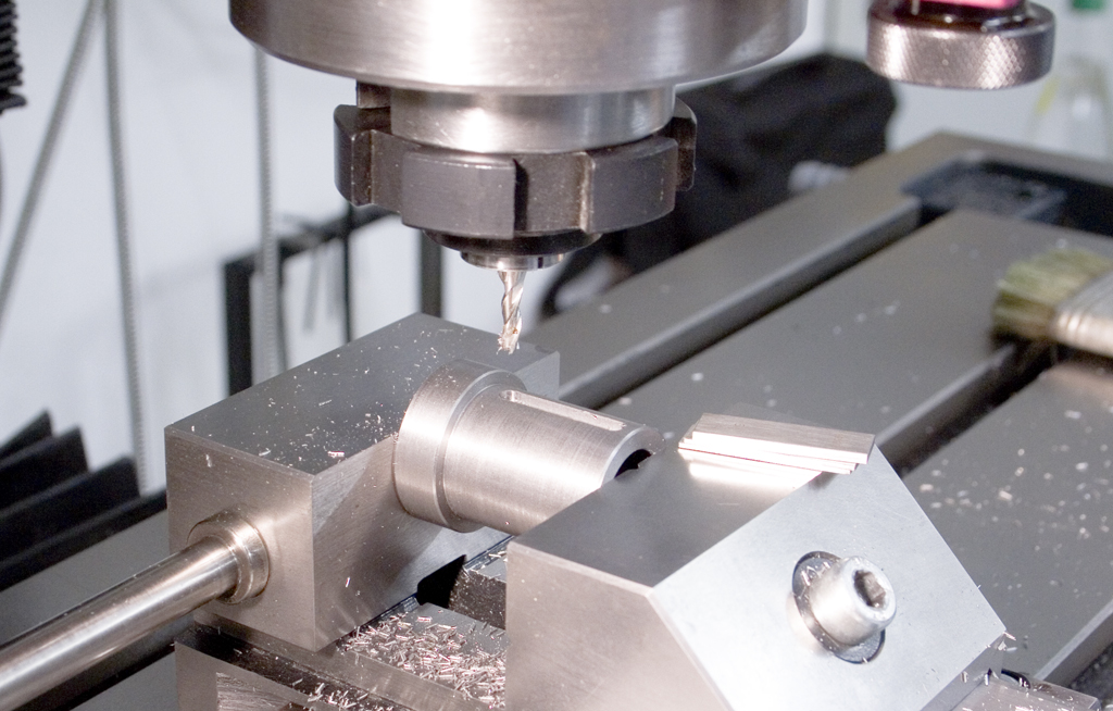
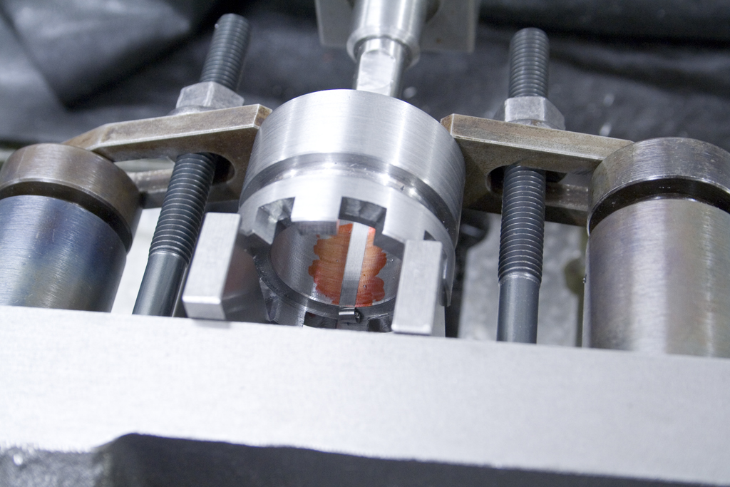
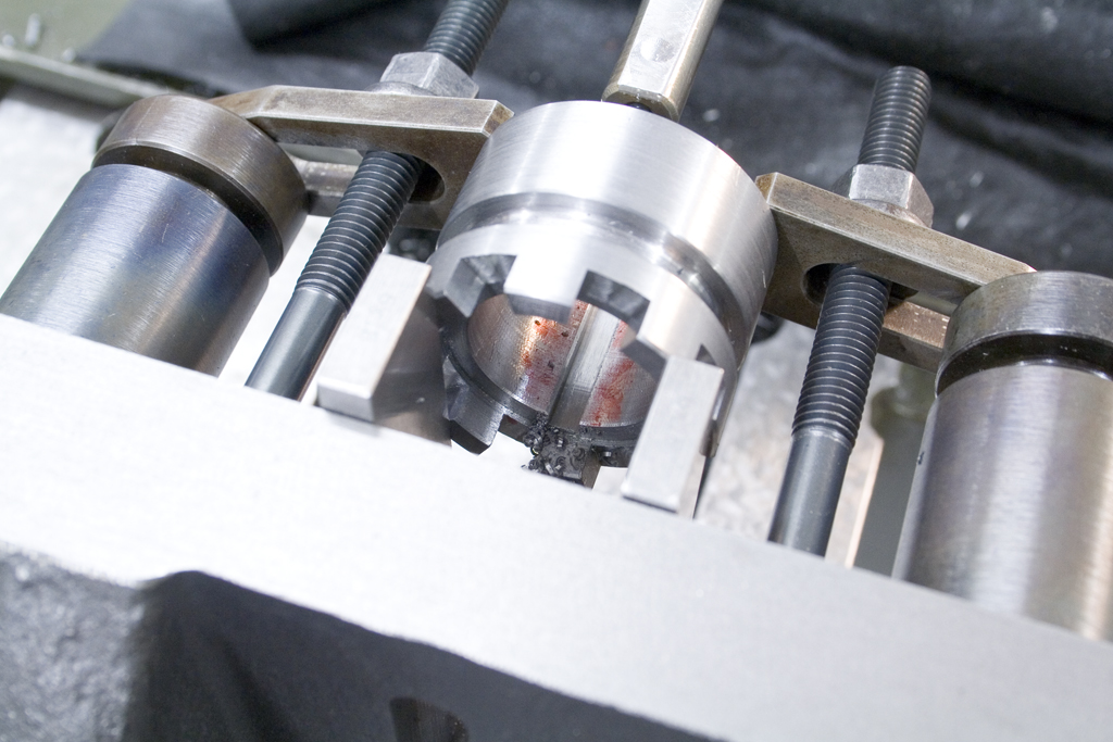
Cutting the keyways into the clutch:
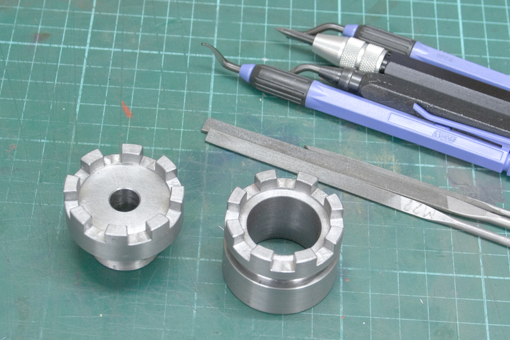
Deburring took some time, using scrapers, deburring tools and needle files:
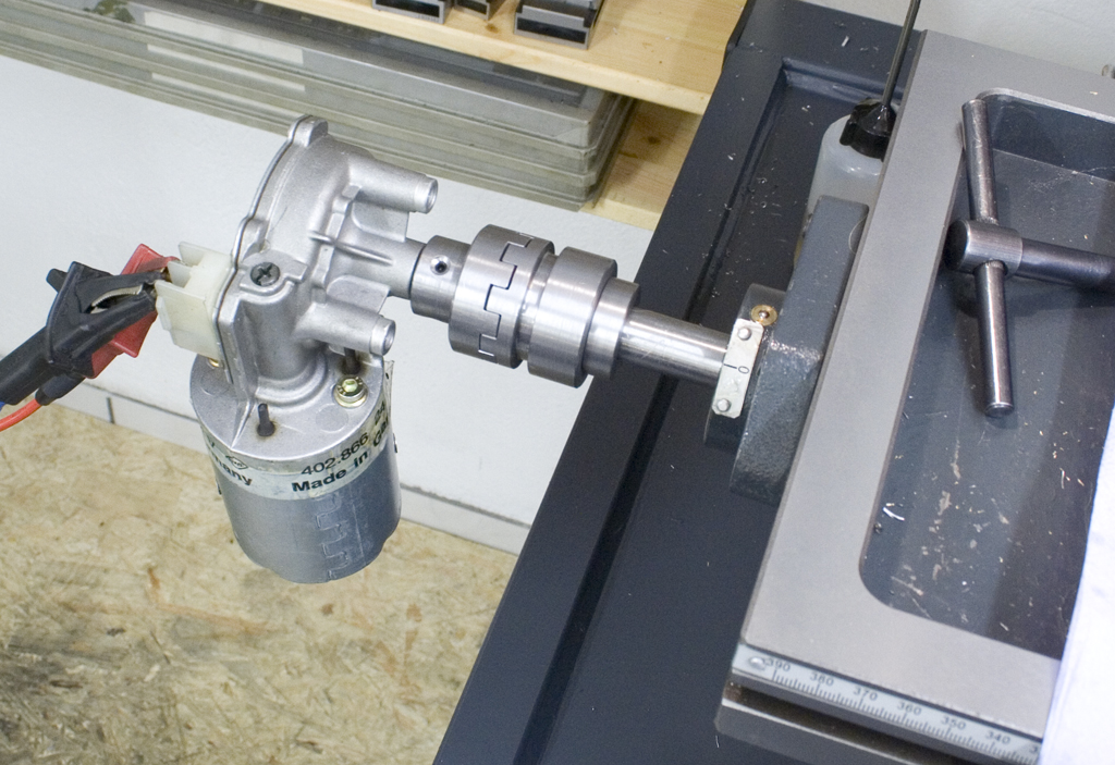
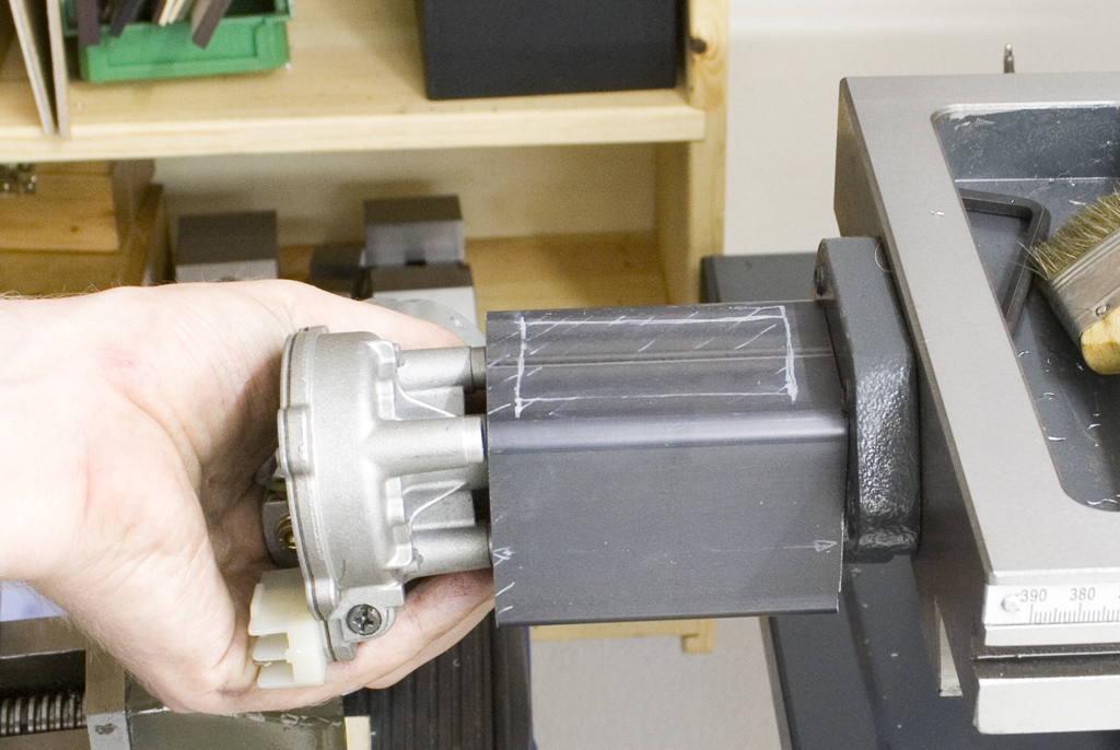
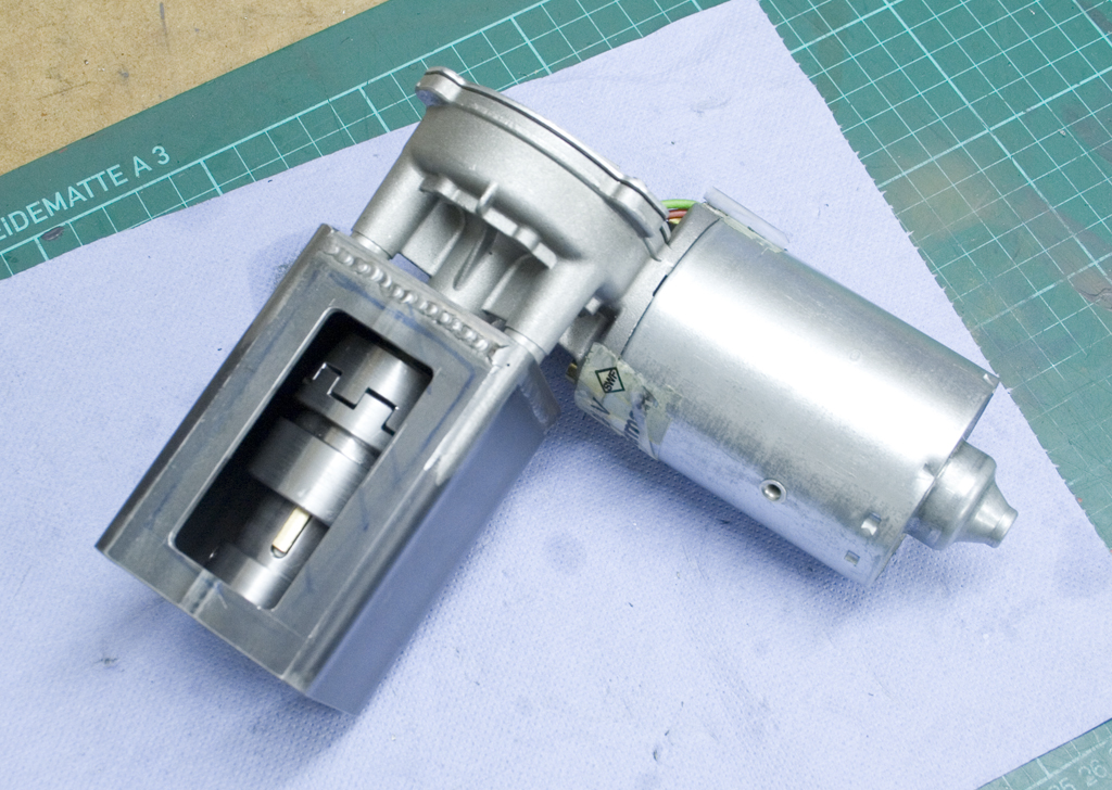
Testfit, with the motor hanging on the clutch:
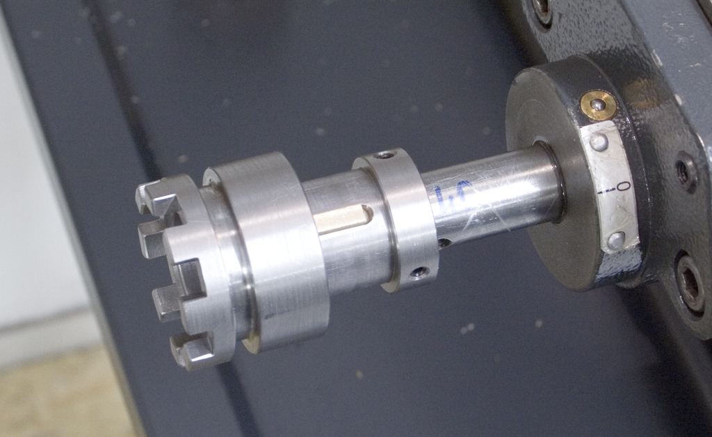
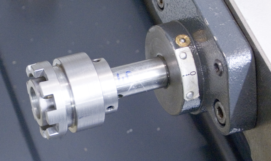
Sliding part of the clutch on engaged and disengaged position:
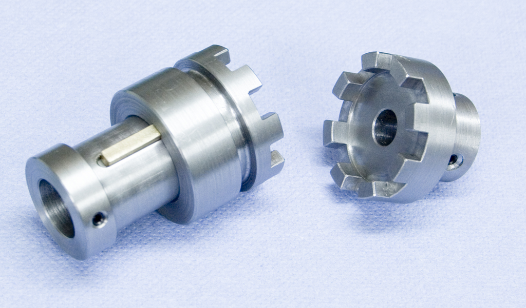
The completed clutch parts:
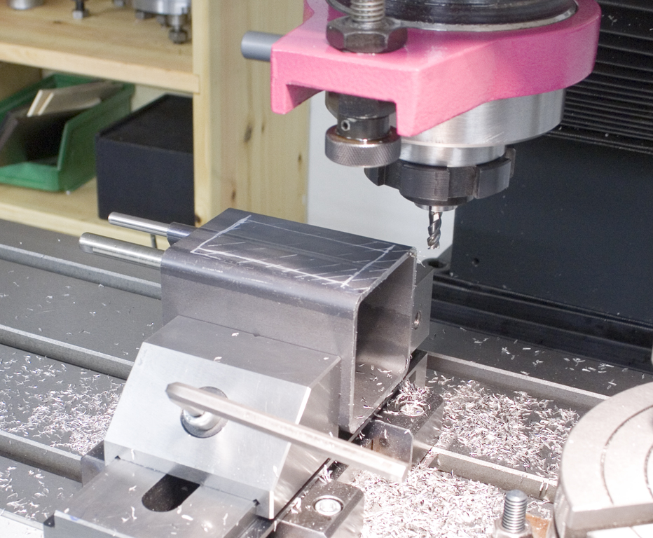
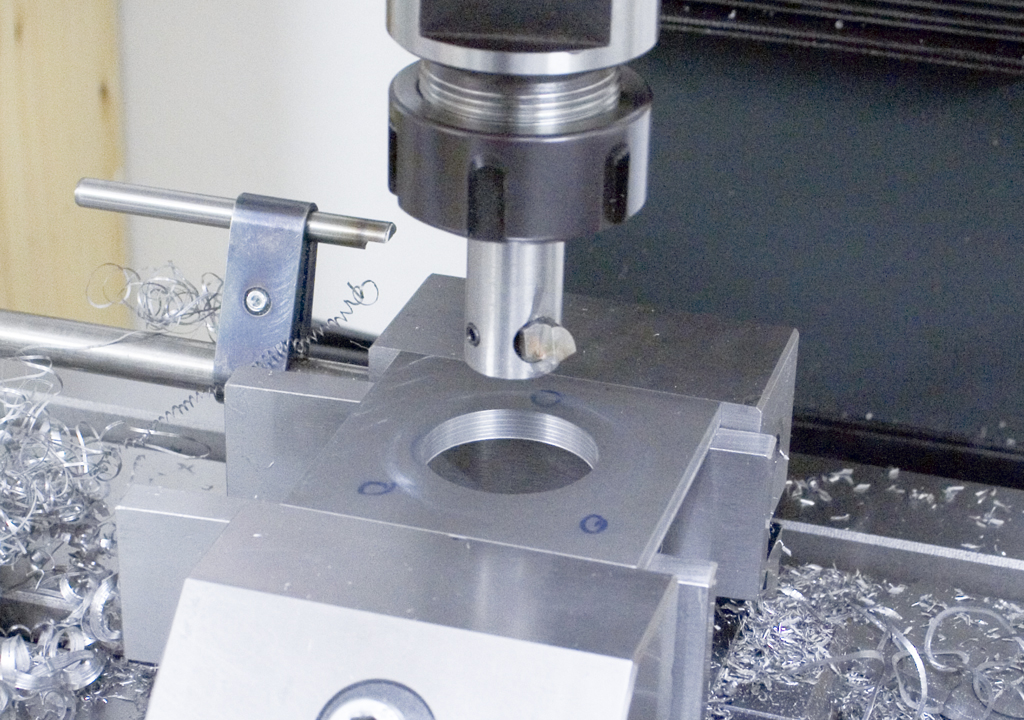
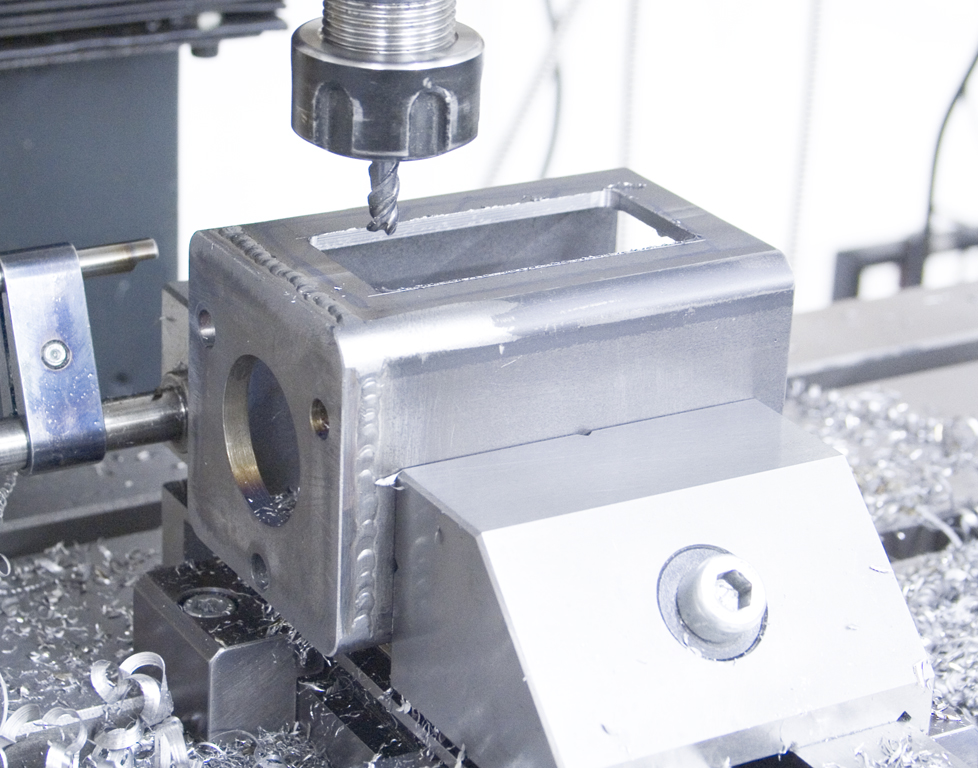
The housing that’s holds the motor and contains the clutch is made out of a piece of 60x60x3mm square tubing:

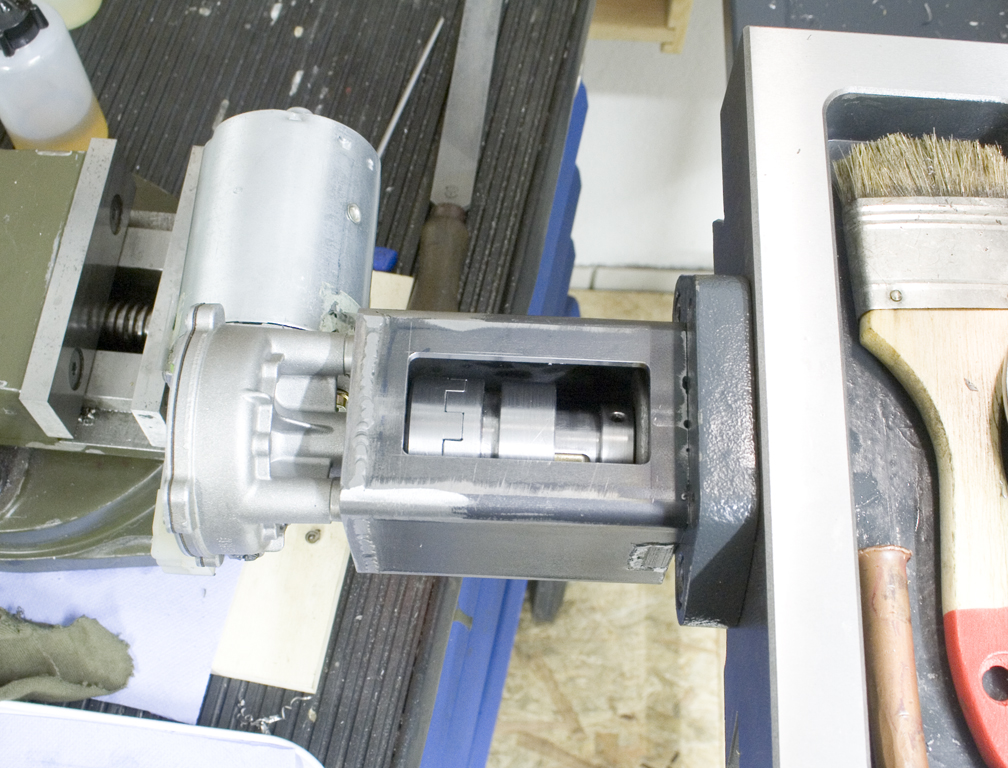
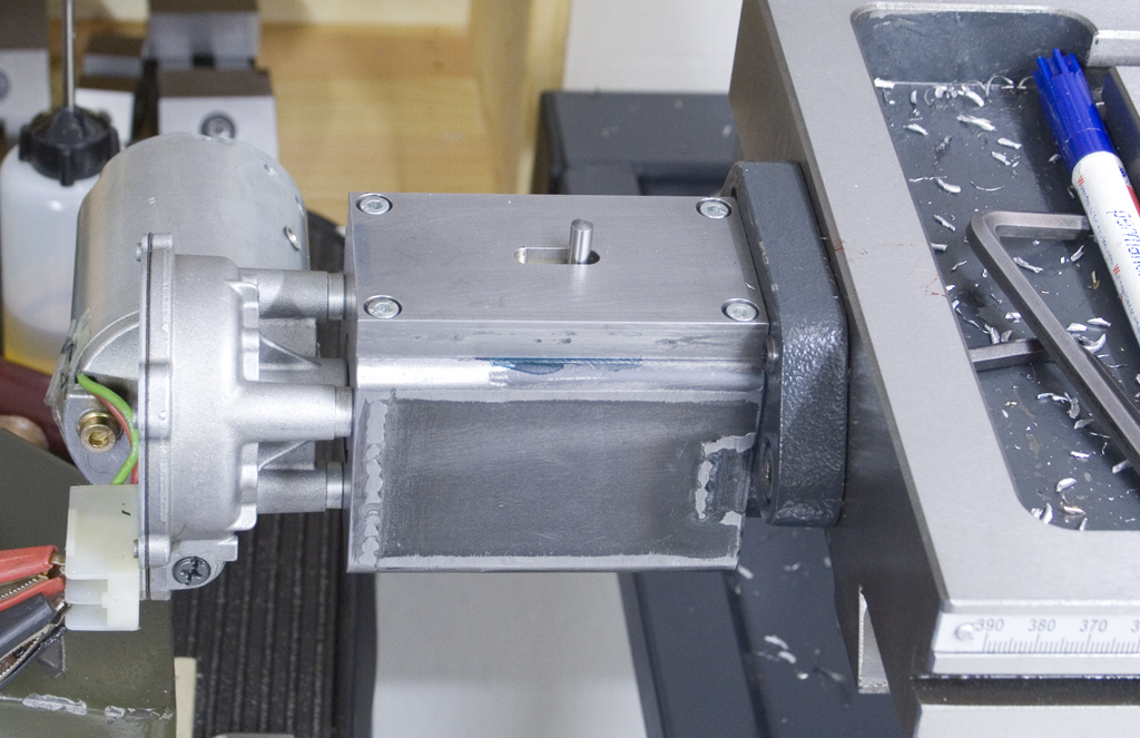
Here the clutch can seen in its disengaged position:
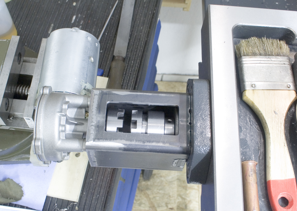
And here it is engaged:
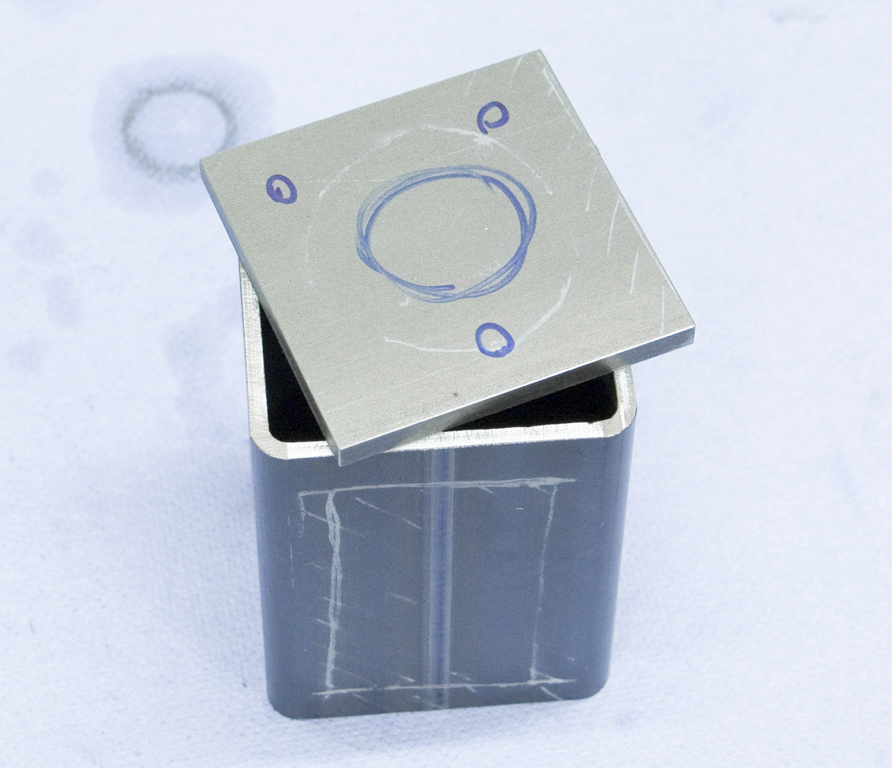
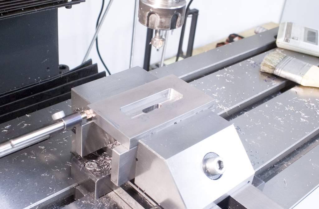
The big cutout in the housing will be covered by a steel plate, which will also hold the lever to move the clutch.
The plate has a slot machined into it and a sliding brass block that’s retained by two gibs. The pin in the brass block is what moves the clutch and also gets moved by the lever:
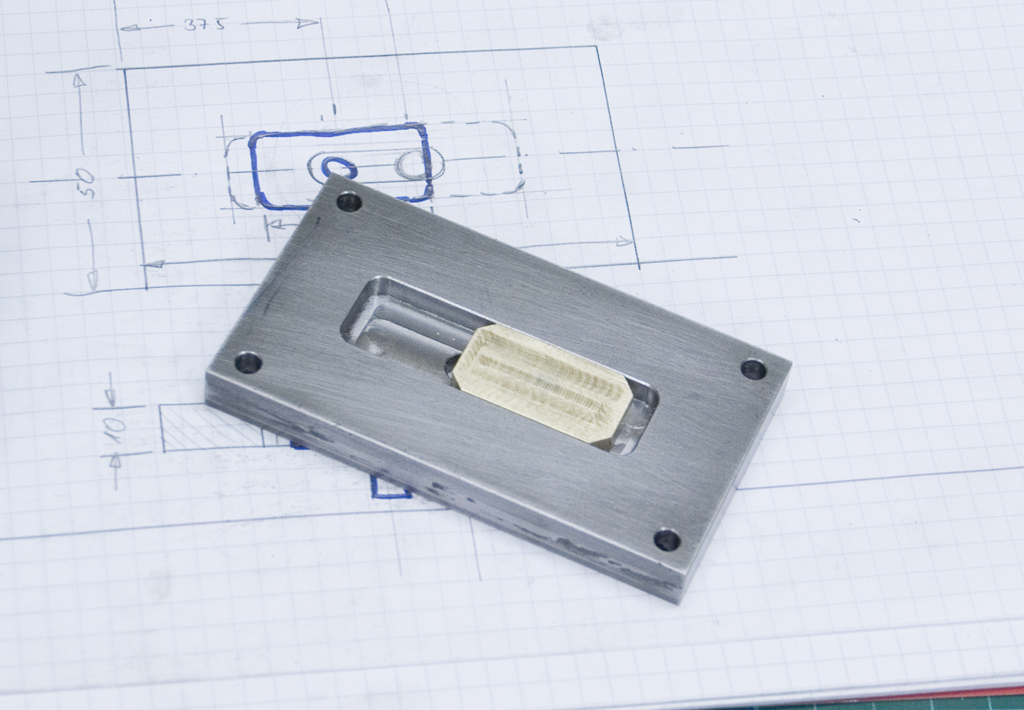
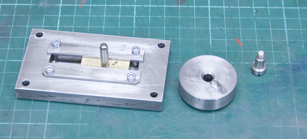
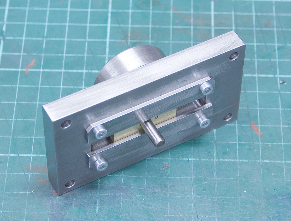
The cover plate with the pin sticking out, the lever is missing:
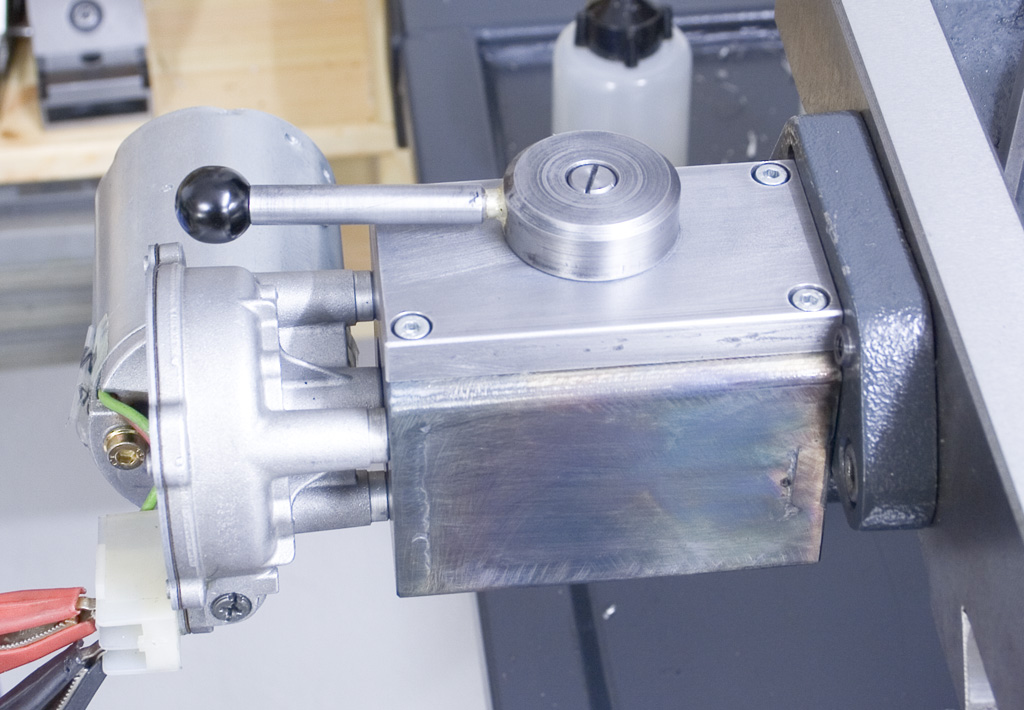
The finished powerfeed with the lever in the open position:
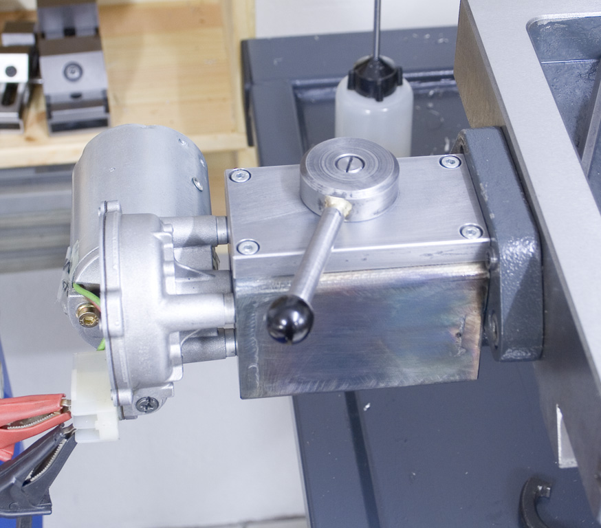
And with the clutch engaged:
And to finish this build, some testcuts in different materials.
Aluminum, 6mm carbide endmill:
Steel, 6mm carbide endmill:
Cast iron, 6mm roughing endmill: