Ideal would be a central one shot lubrication system, but that is not a definite need on a manual machine (But more so on a CNC machine with its rapid movements and repeated short movements which tends to break the oil film).
I will go for oil grooves in the ways and some zerk fittings (Zerk fittings work for both grease and oil, but you want of course oil for your ways, no grease.), and I want both, the horizontal and the angled surfaces of the dovetail to be lubricated (Including the gib).
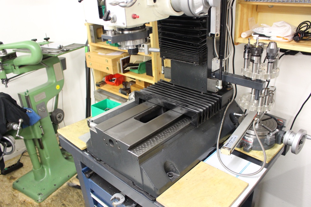
First step: Taking the X/Y Table apart. Carefull handling of the glas scales is needed, here it pays off if you have saved the transport locks for the scales:
The table and saddle – All the oil grooves and zerk fittings will go into the saddle and the gibs:

A quick note about the shape of the oil grooves, the book “Werkzeugmaschinen 2” by Manfred Weck states that Z-shaped oil grooves are ok for most applications, there are other shapes that work better but result in more work.
I will go for the Z-shape as the machine is not a highvolume production machine.
More important is the cross section of the oil groove, especially the top edge where it passes over to the sliding surface.
A sharp edge is the worst thing there, it acts like a wiper which removes the oil film that we want to build up.
It is better to chamfer the top edge of the oil grove in a flat angle of about 10…30° which can be done very easily with a handscraper – Just set it on top of the edge, tip it over a few degrees and push it along the edge, the result is a small, clean chamfer.
Even better would be a rounded over edge which goes tangential into the sliding surface, that can either be done on a CNC by 3d machining with a ball endmill or with a special endmill or very careful with a lot of handwork (Riffler files, scraper and small stones).
I went for the chamfered edge as I did not want to go trough the trouble of rounding over the edges.
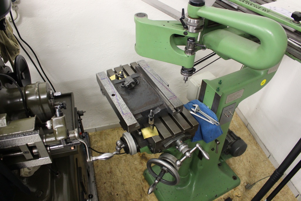
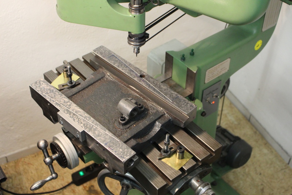
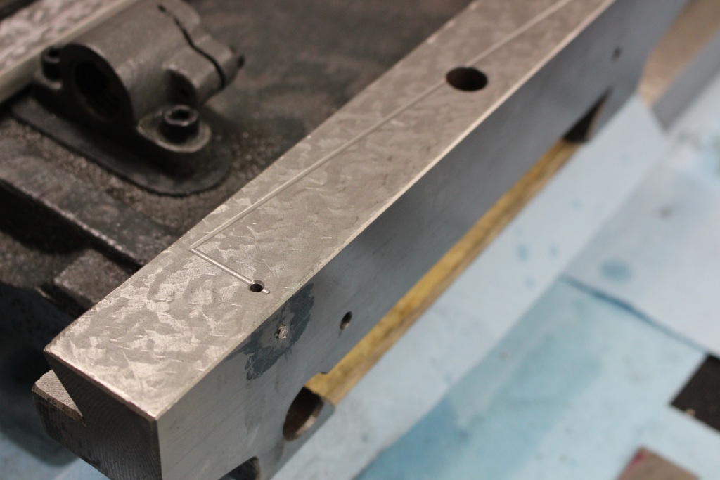
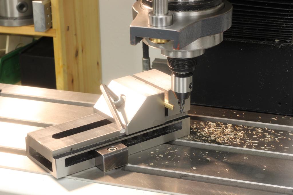
At first I machined the oil grooves on the engraving machine with a 3mm ball endmill, it worked very well but it is a lot of setup involved and you cannot reach into the angled sliding surfaces of the dovetail:
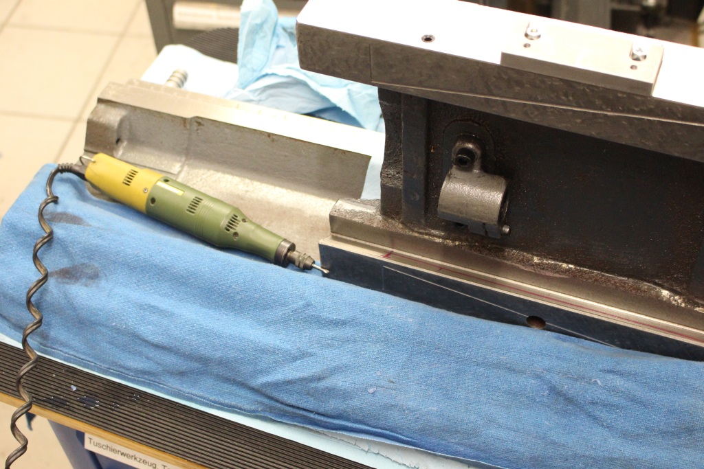
On the angled sliding surfaces I used a Proxxon die grinder – Pretty much my first powertool ever, I think I bought it about 17 years ago and it is still going – With a carbide burr I was able to cut the grooves just following a layout line:
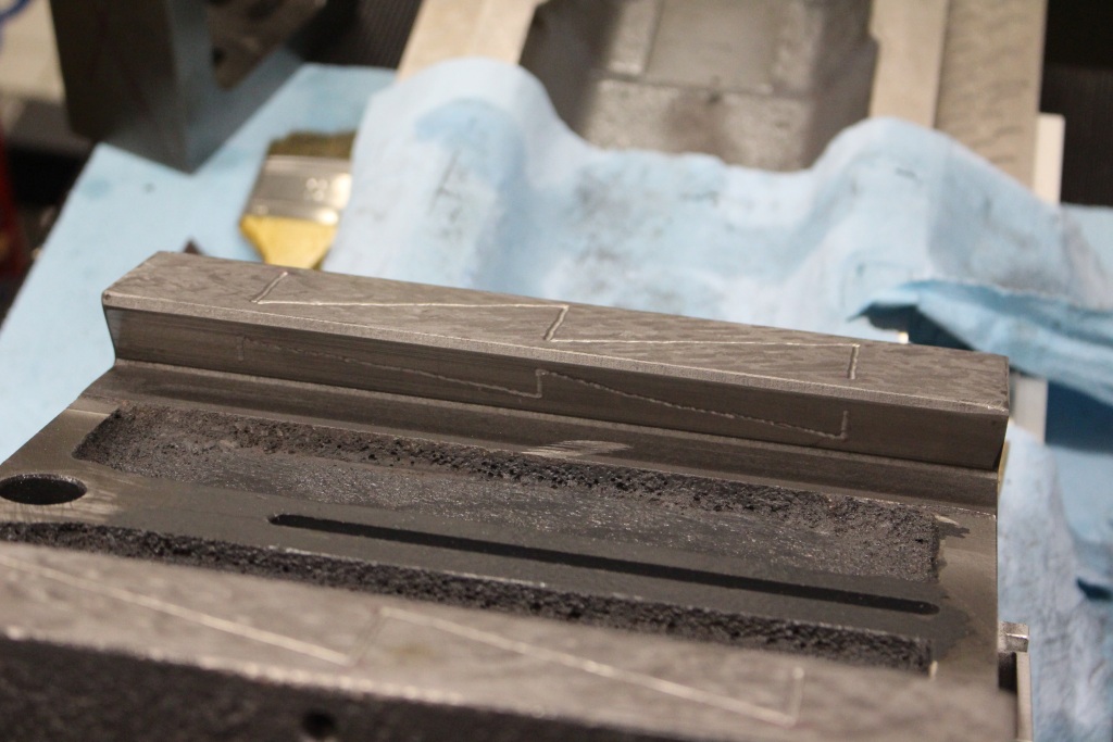
Here you can see the Z-shaped oil groove in the angled surface:
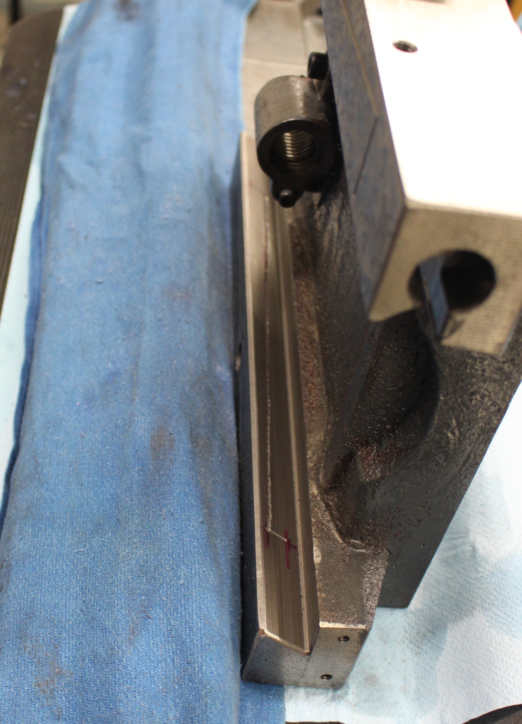
Down in the corner there is a 6mm thread for the zerk fitting – Intersecting that threaded hole I have another hole that goes up to the flat sliding surface and another one that goes over to the angled surface:
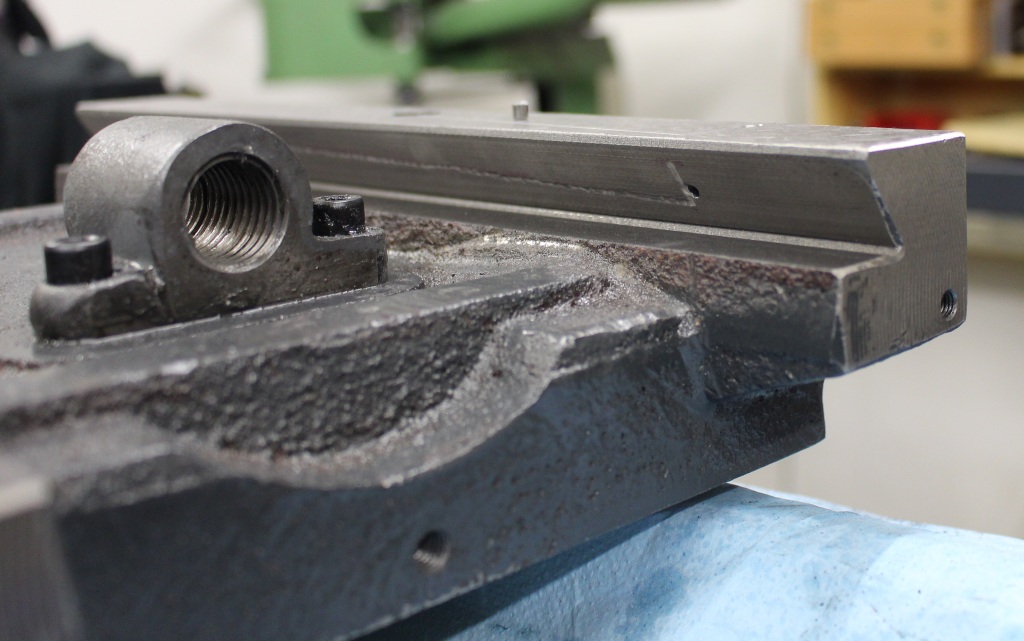
The hole for the angled surface had to be drilled from the outside and needs to be plugged with a piece of cold rolled steel and some Loctite 648. After the Loctite has cured the extra material of the plug can be taken off with a file:
Here you can see the flat sliding surfaces in the Y-direction, here I decided to make the Z-shape a bit narrower, which should be a bit better in theory. As you can see I did all the grooves no freehand with the die grinder as it is good enough and way faster than doing multiple setups on the engraving machine:
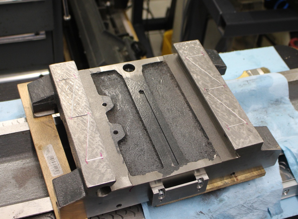
In this picture you can see three of the zerk fittings that lubricate the X and Y ways – There is a fourth fitting on the opposing side of the saddle:

While being on the topic of lucrication, I added a felt wiper for the unprotected Y-axis of the machine.
A piece of 5mm natural felt and some 2mm aluminum sheetmetal where all that’s needed:
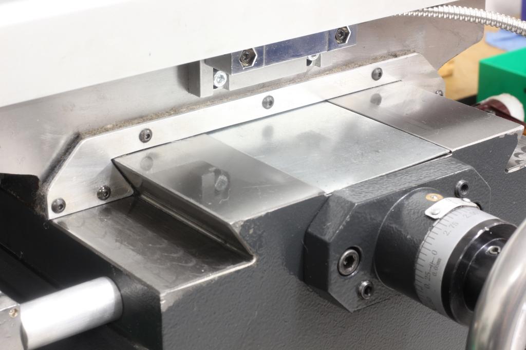
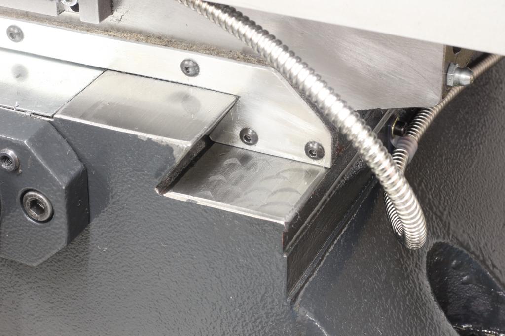
It is a good idea to make the retaining plate for the felt with very little gap to the actual sliding surface, so most of the chips get pushed out of the way by the sheetmetal and only very little has to be taken by the felt.
But it is still important to remove the felt wiper from time to time, clean it and put it back onto the machine. Otherwise it will pack up with dirt over time.
And still working on the machine I decided to do something against the stupid locking screws for the axis – The screws act directly against the gip which tends to dent the gib and move the table slightly out of place while clamping it.
It is better to have a small pusher with the angle of the dovetail machined on one face to go between the gib and the screw.
To make those pushers, I took a piece of 6mm brass (Which fits into the 8mm threaded holes for the locking screws) and machined a 55° angled surface on one side. Then I parted them off on the lathe and was done:
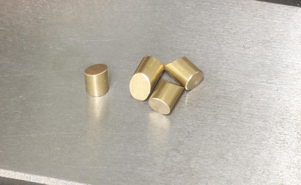
With those pushers between the screws and the gibs the locking action feels way more convincing and the table does tend to move 1/100mm while clamping.
With all those improvements I got the machine again a bit more on the bright side.