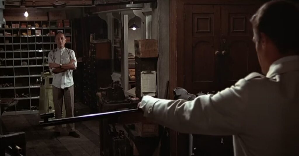
Something different this time – A scene from a movie classic: The Man with the Golden Gun from 1974
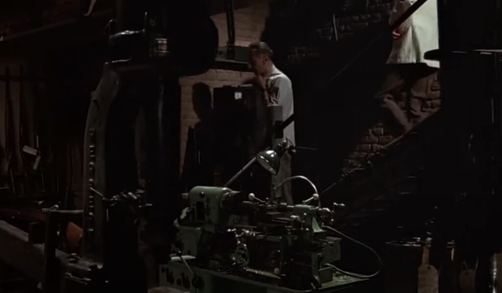
This scene does not look like a movie set, but as if it was filmed in a real shop rented for filming.
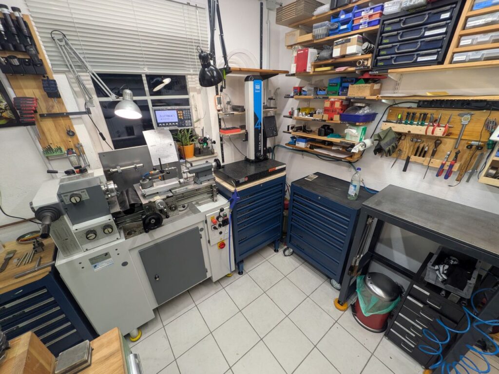
Right on entry, we can see a Boley lathe:
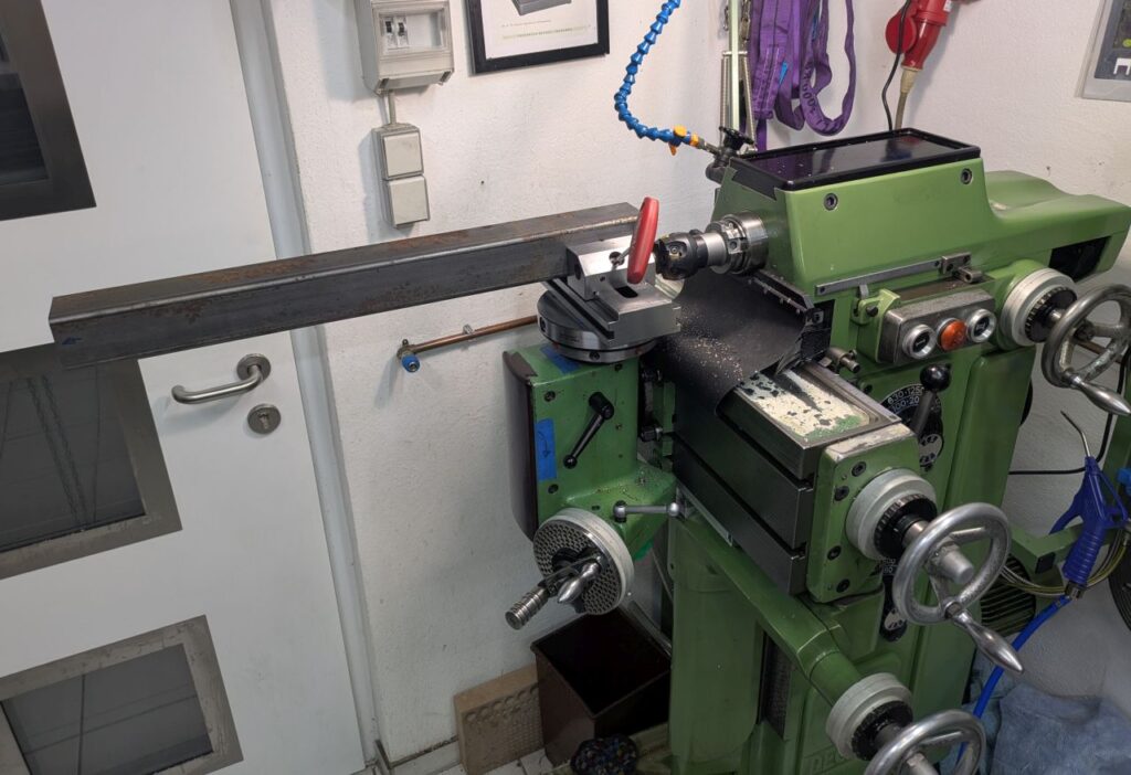
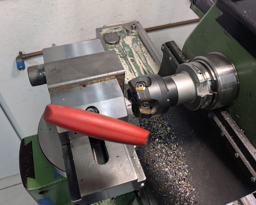
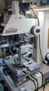
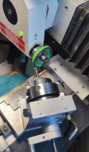
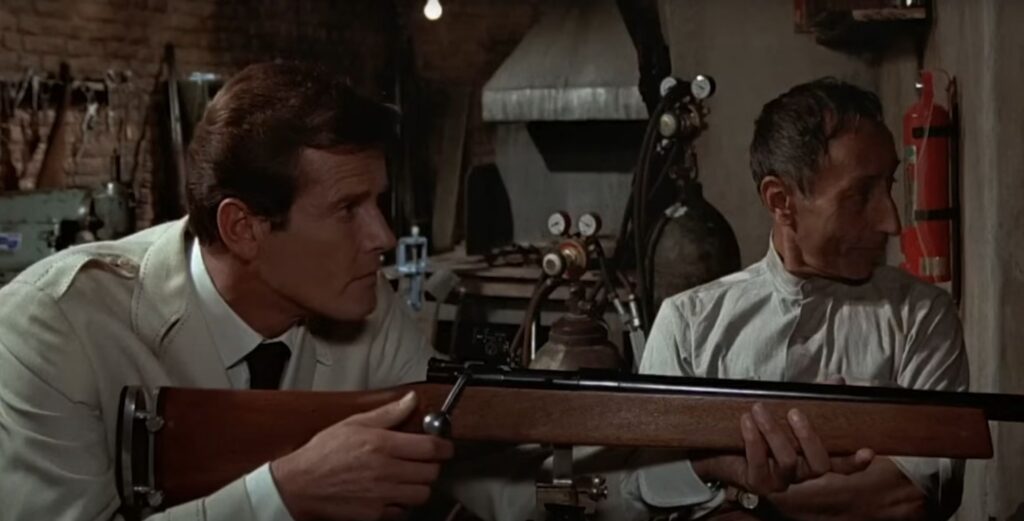
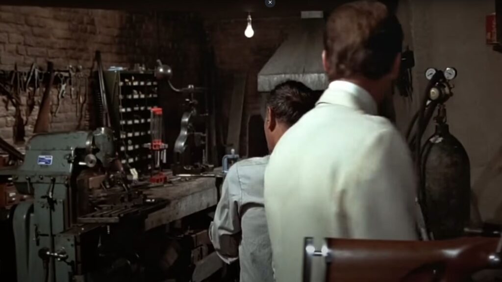
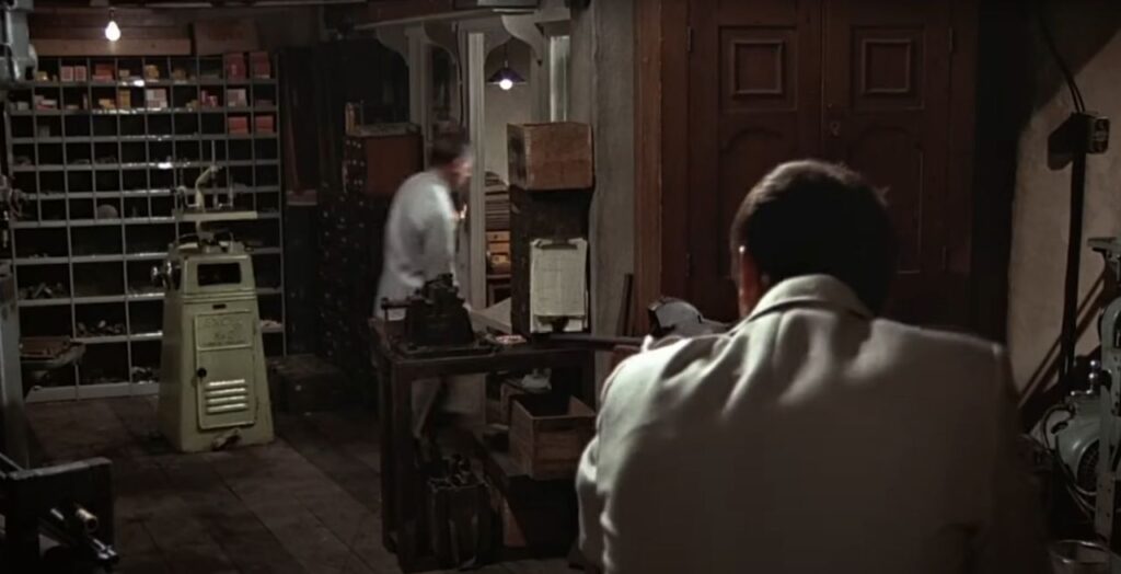
When Roger Moores character is aiming down range, we can see a what appears to be a Deckel FP1 on the left and an Oxy-Fuel setup along with a forge in the middle of the frame.
The second picture gives a better view on the FP1 – It could also be an Alexander “Master Toolmaker” (https://www.lathes.co.uk/alexander/) since large parts of the movie where filmed in the UK and Alexander being a British Company making a copy of the Deckel FP1.
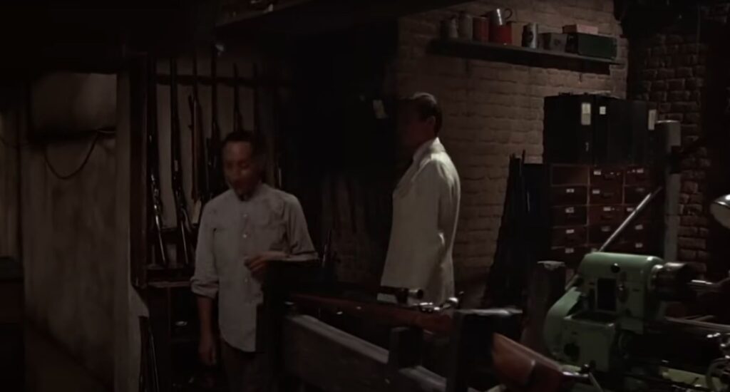
While getting some information from Lazar, the gunsmith played by Marne Maitland, we can also see an Excel No.2 die filer.
The entire scene can be reviewed on Youtube:
THE MAN WITH THE GOLDEN GUN – “I’m now aiming precisely at your groin…”
Spotting and centering small drills is not a trivial task. Normal NC spotting drills have a wide web and tend to create a spot with a flat bottom that’s unsuitable to guide small drills.
There are specialized one or two flute carbide spotting drills for small diameter work, but they tend to be rather expensive and extremely delicate.
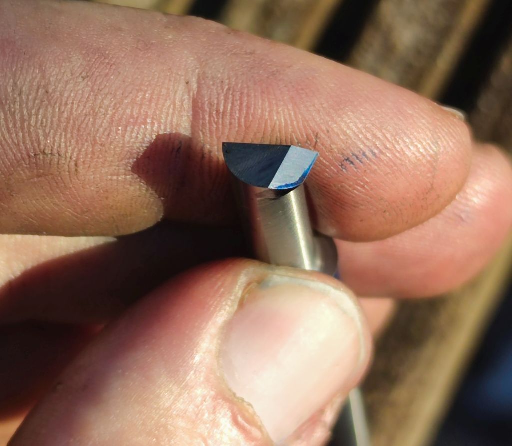
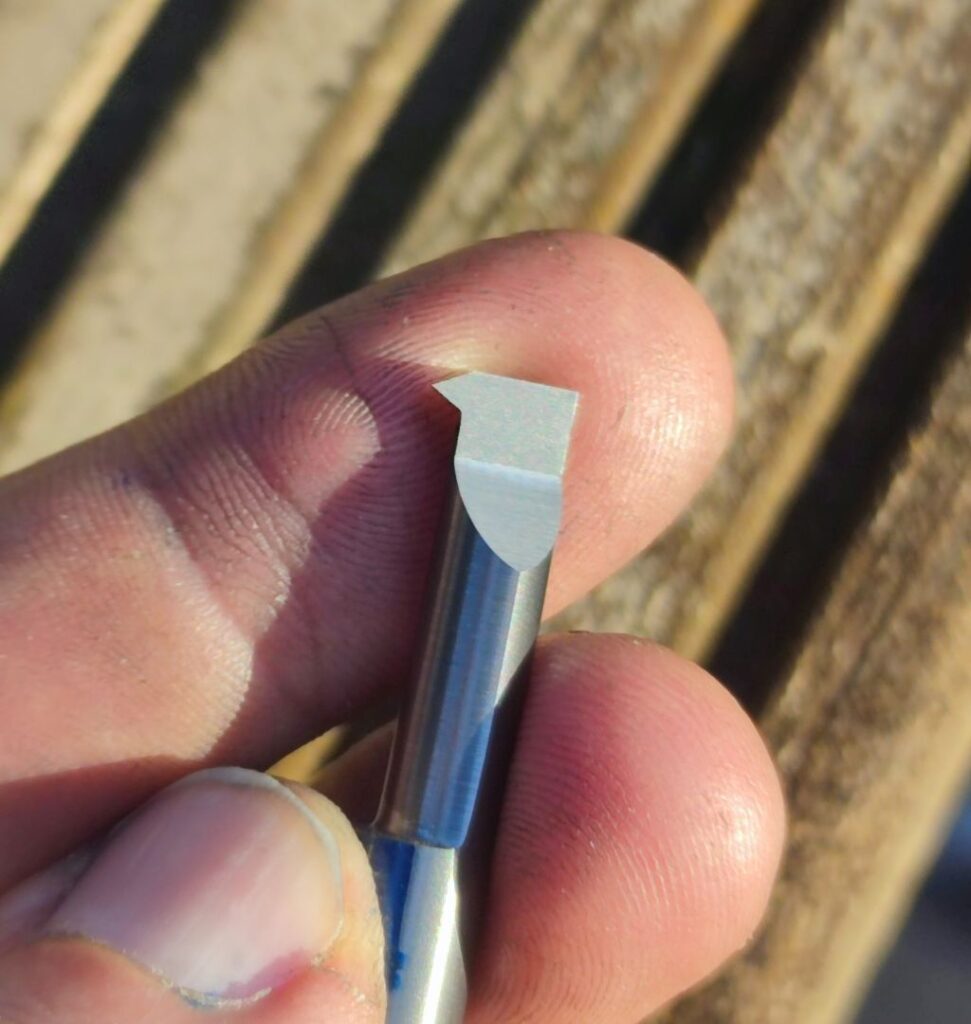
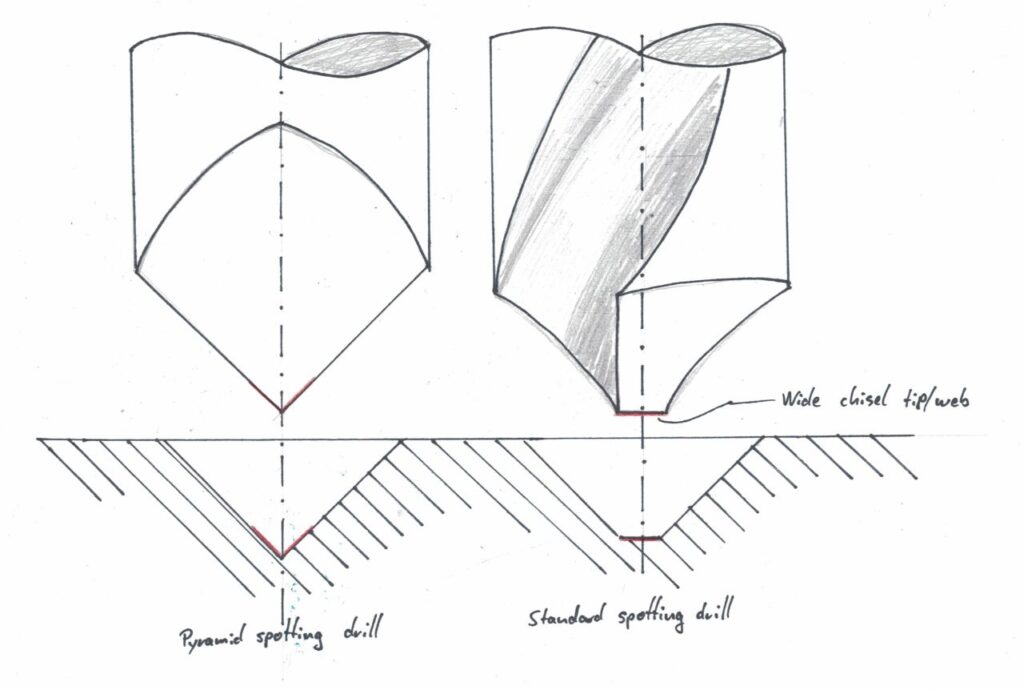
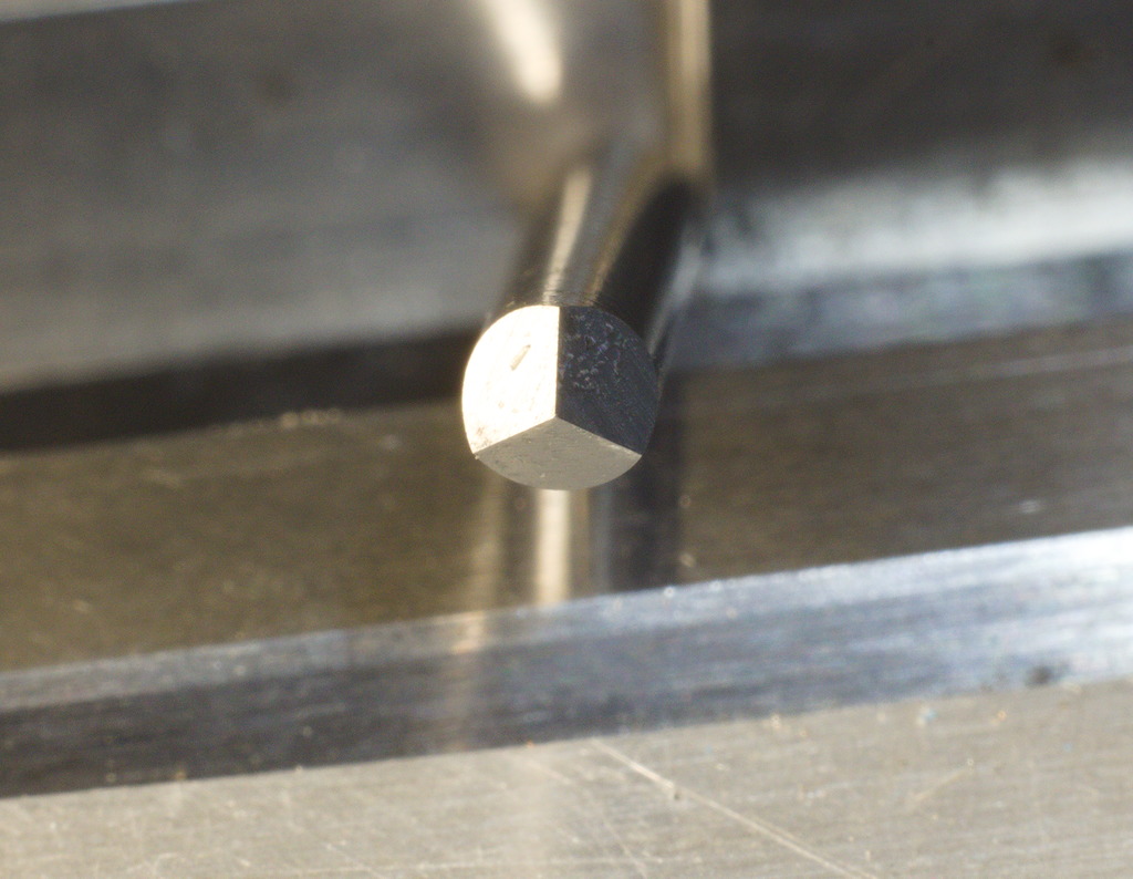
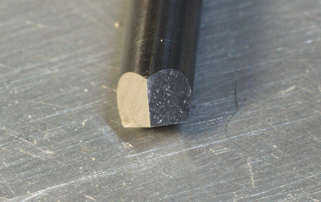
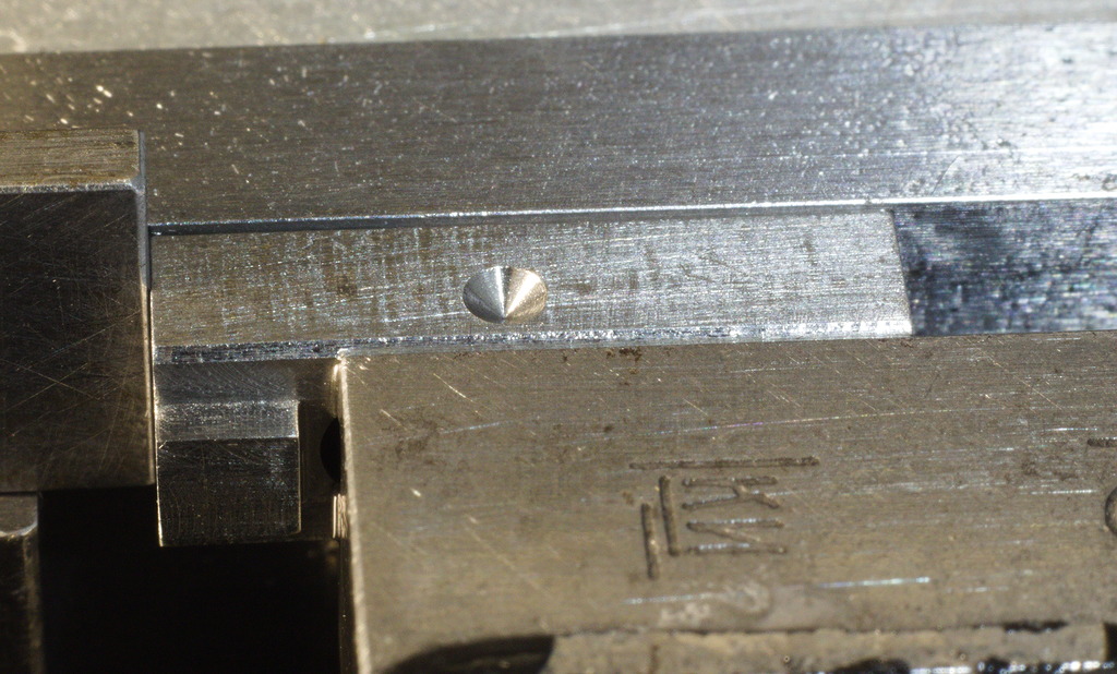
One alternative that I was made aware of is the pyramid spotting drill – This shape is referenced in literature a few times, not only as a spotting drill, but also as a micro engraving tool for hard materials.
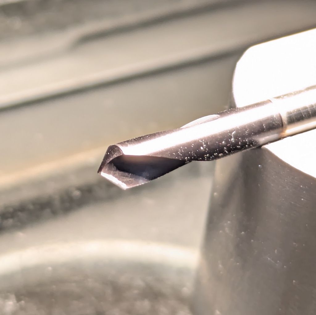
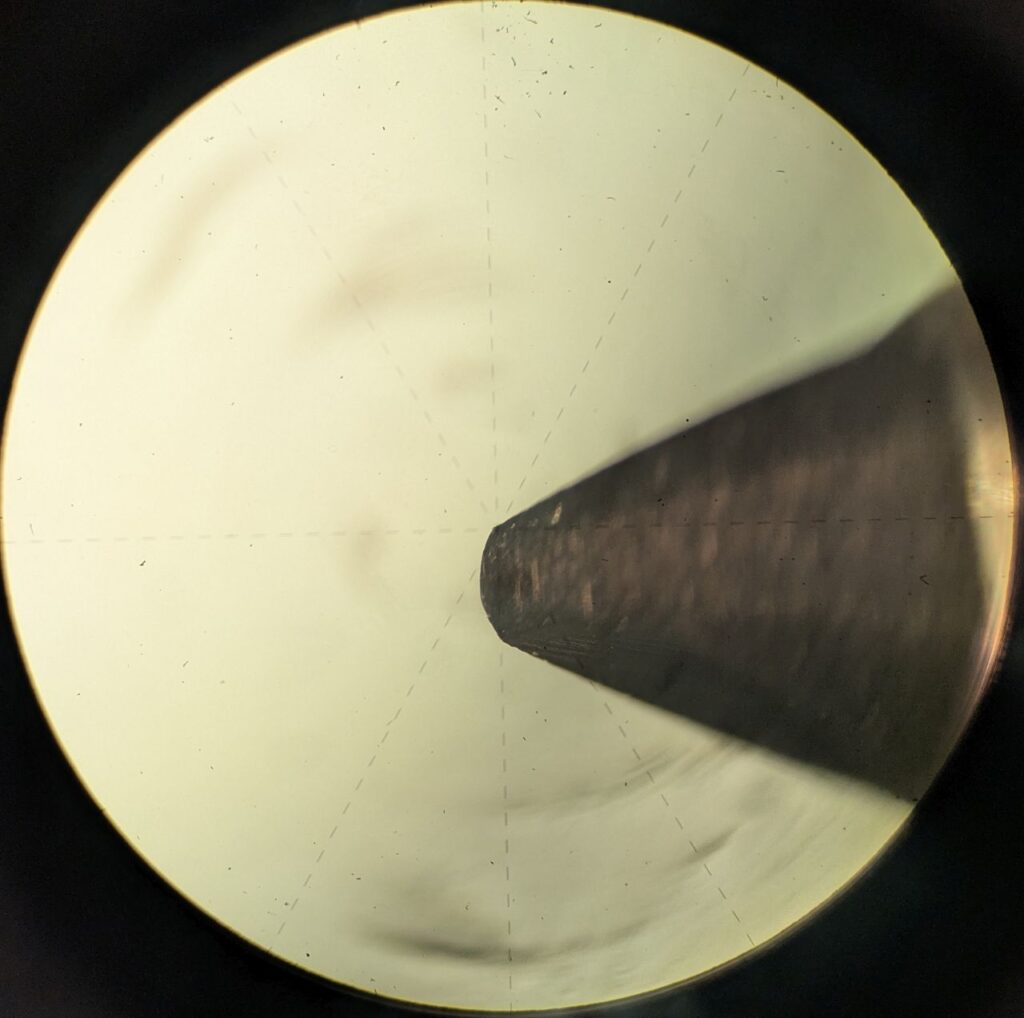
Trying to visualize the problem with the chisel tip/web of standard spotting drills – They leave quite a large flat spot, that might already be too big to guide small drills.
How big is that flat spot left by the web? I am glad you asked.
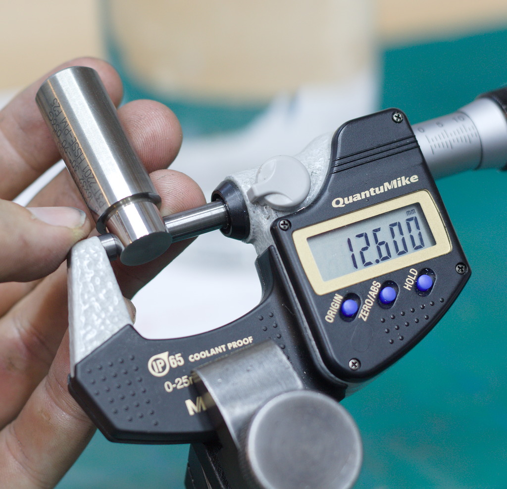
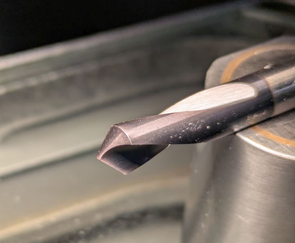
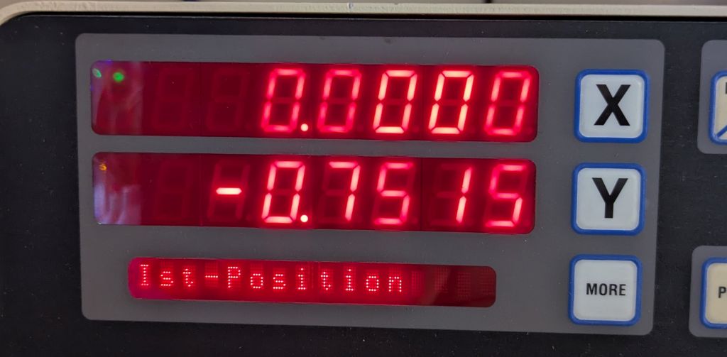
On a good quality 6mm 90° spotting drill I measured a web width of 0,75mm:
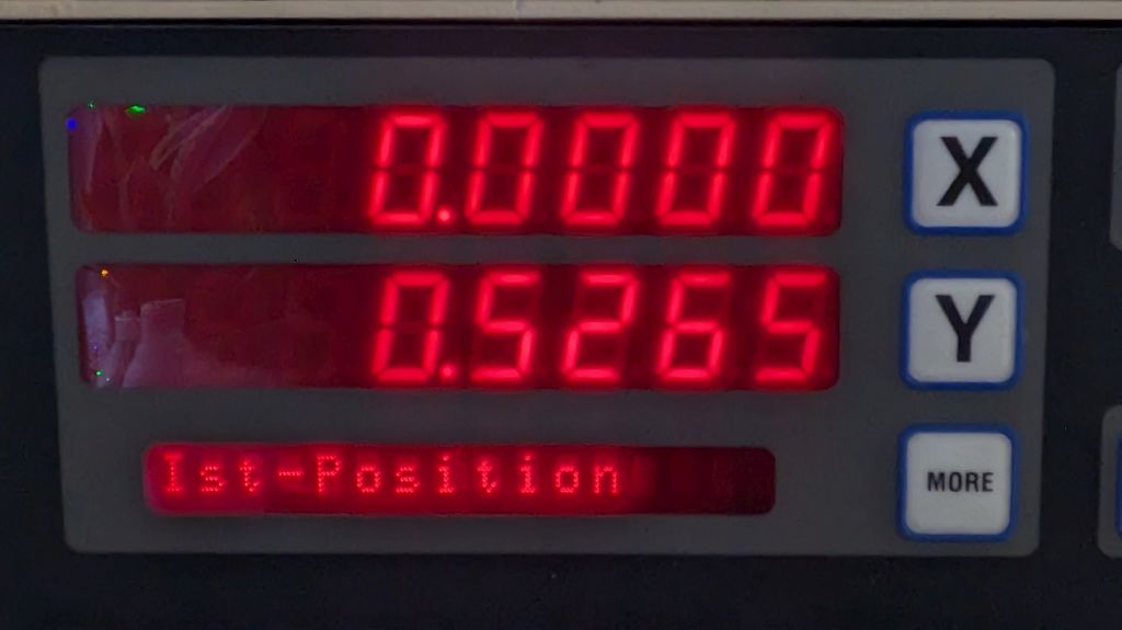
A similar 3mm 90° spotting drill still had a 0,52mm wide web:
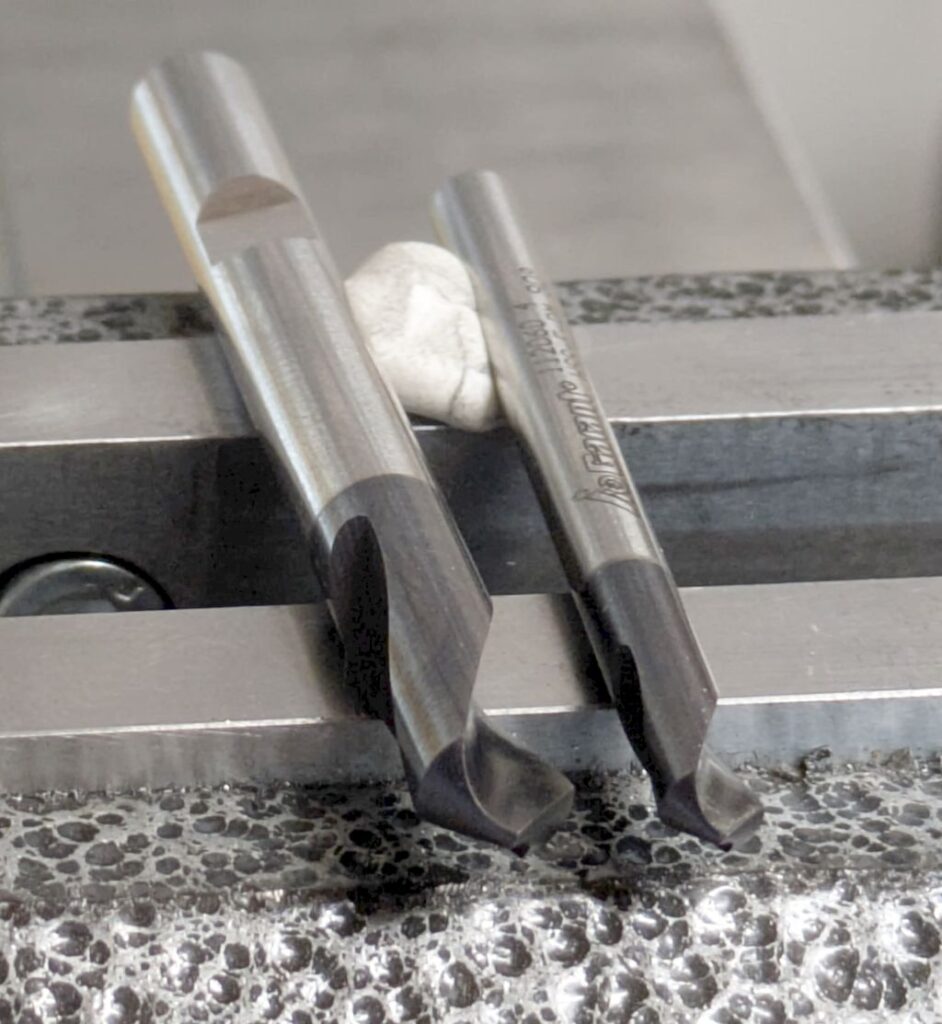
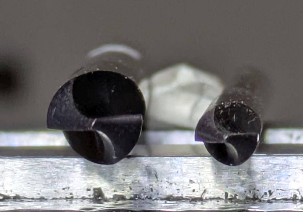
The two spotting drills measured:
You can clearly see the wide web of the drill in the second picture.
As mentioned, there are spotting drills with thinned webs or single flute versions that have almost no web but are extremely vulnerable to damage and wear, so I try to avoid them.
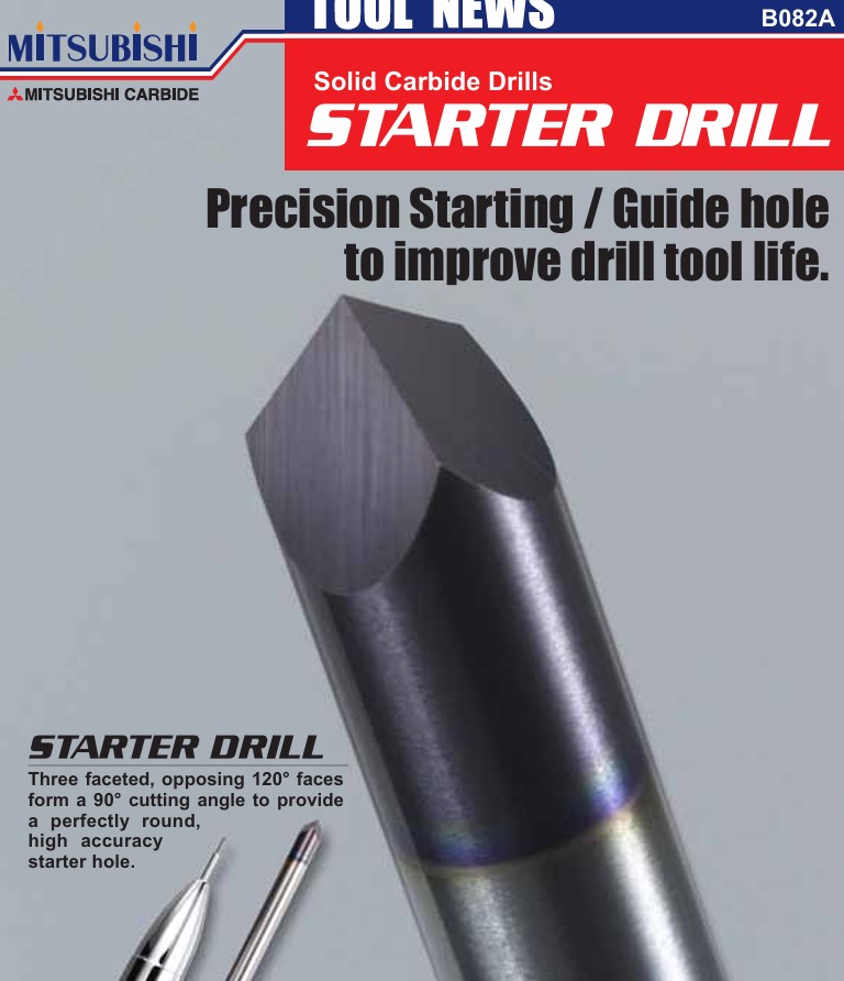
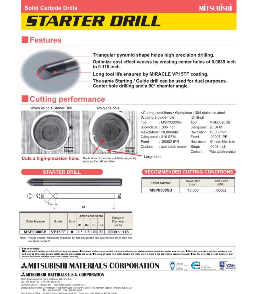
The pyramid spotting drill is available as a commercial tool by Mitsubishi, in a nice, coated version.
It also comes with a technical datasheet that points out the advantages of this shape and recommendations for speeds and feeds.
For commercial use, I would absolutely recommend purchasing these drills and not bother grinding them in-house.
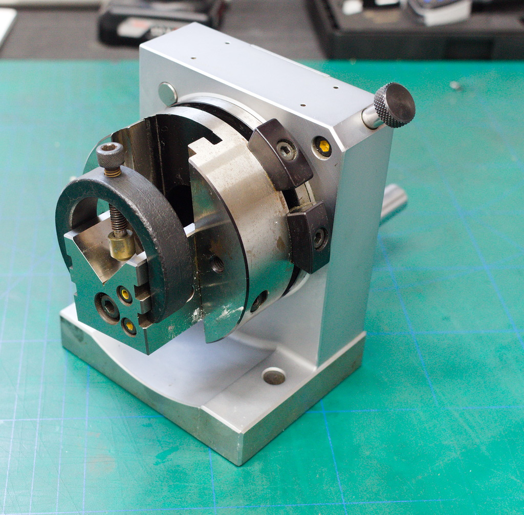
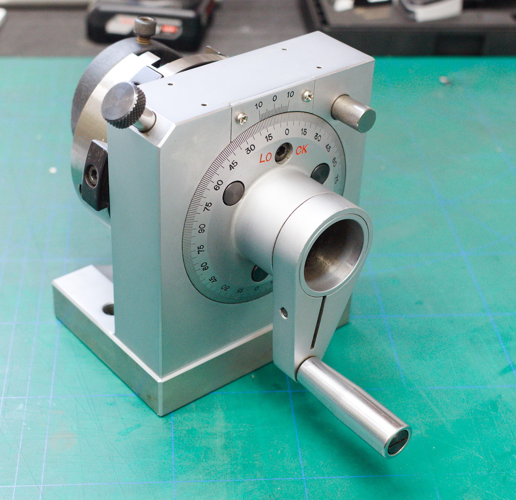
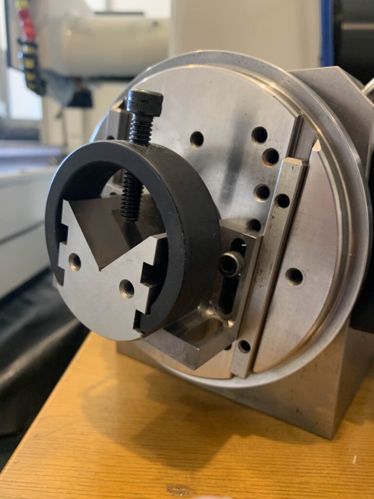
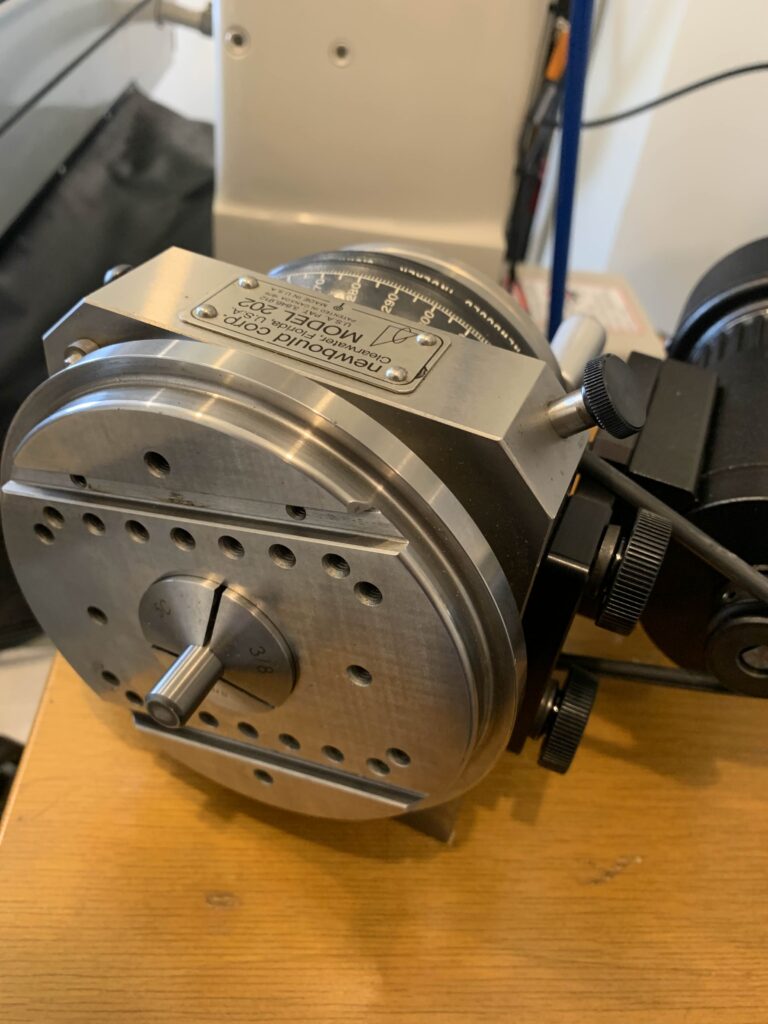
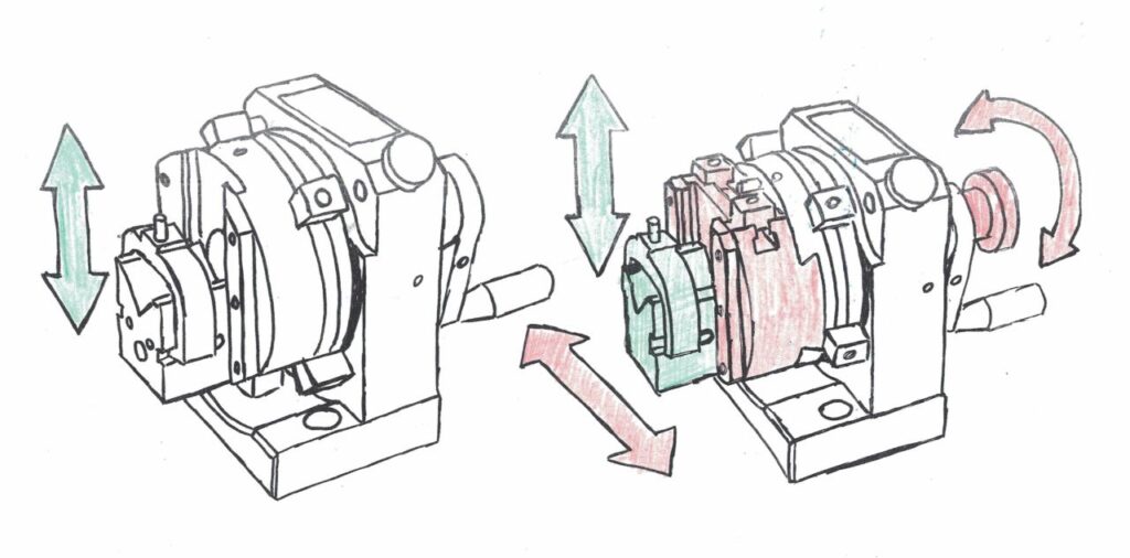
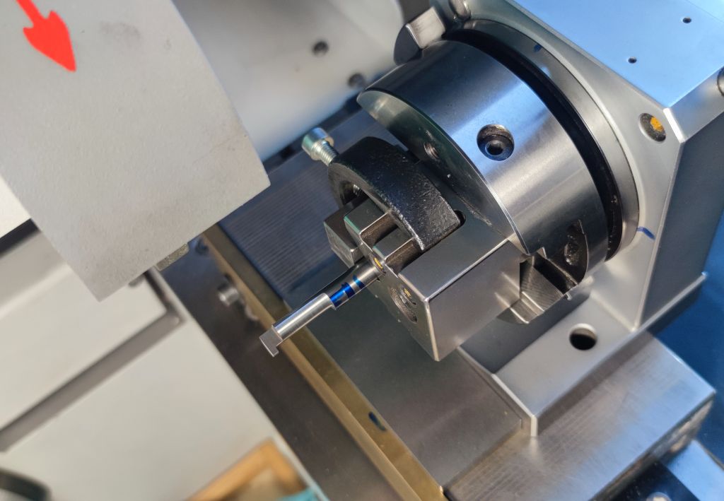
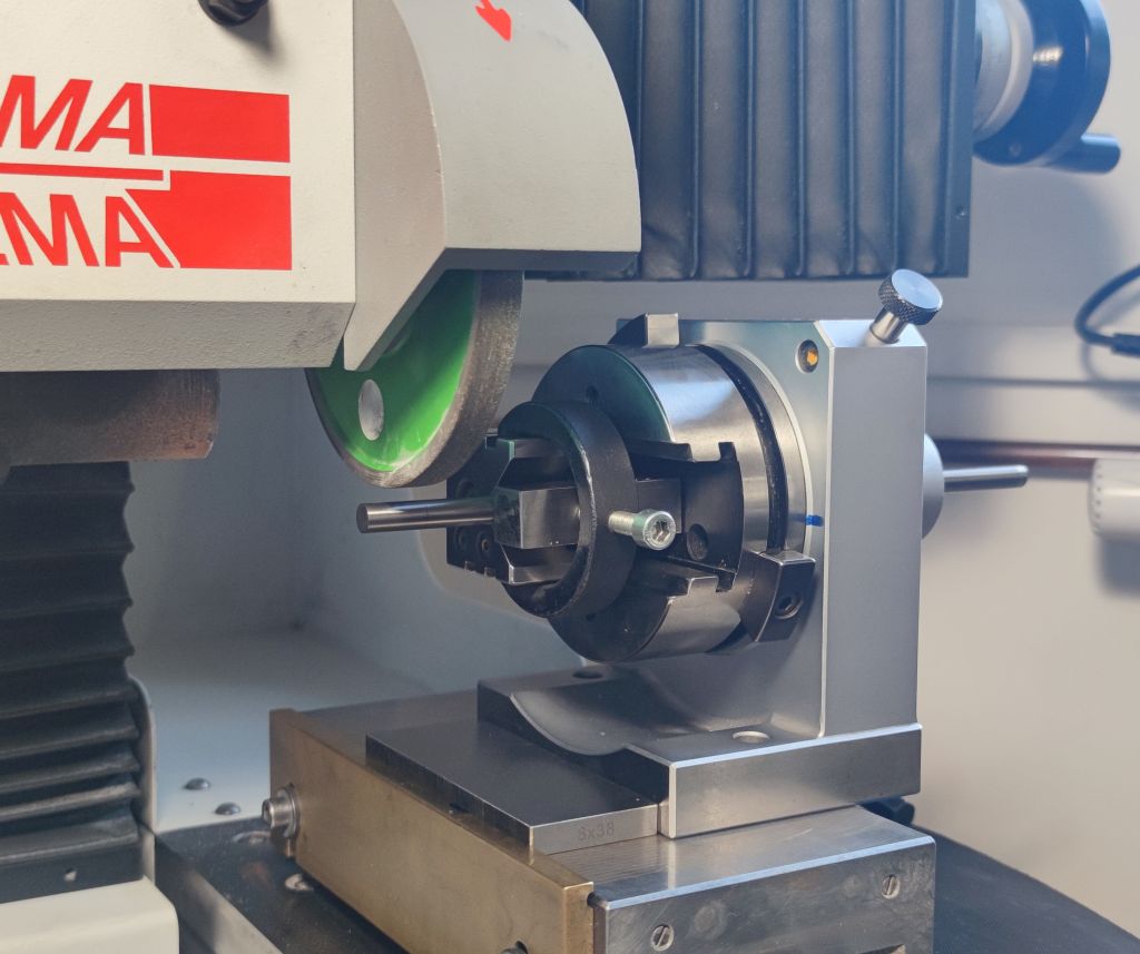
But, as hobbyists or operating a small shop, it can be an option to grind them out of carbide stock – The shape is very simple and forgiving. All that’s needed for grinding is a way of indexing the blank in 120° increments and some sort of grinder.
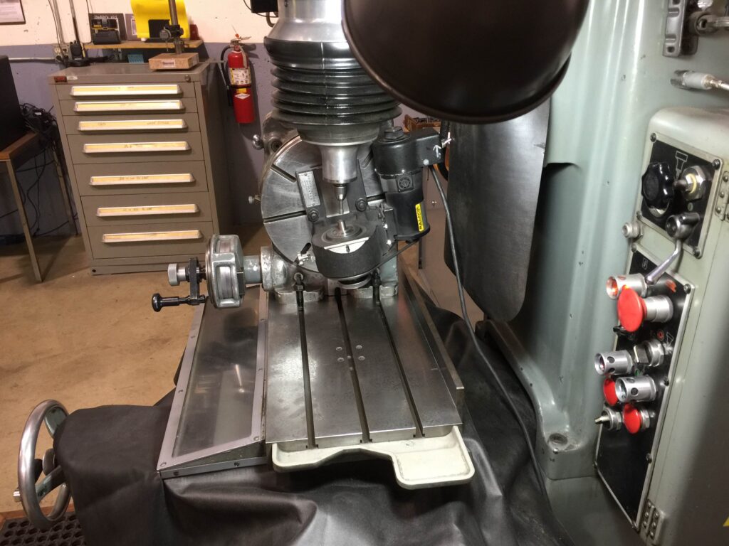
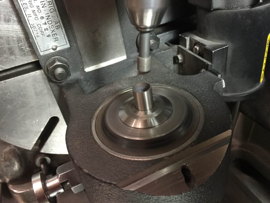
A D-Bit grinder, surface grinder with spin fixture, a milling machine with a dividing head or a real tool and cutter grinder will all do a similar nice job.
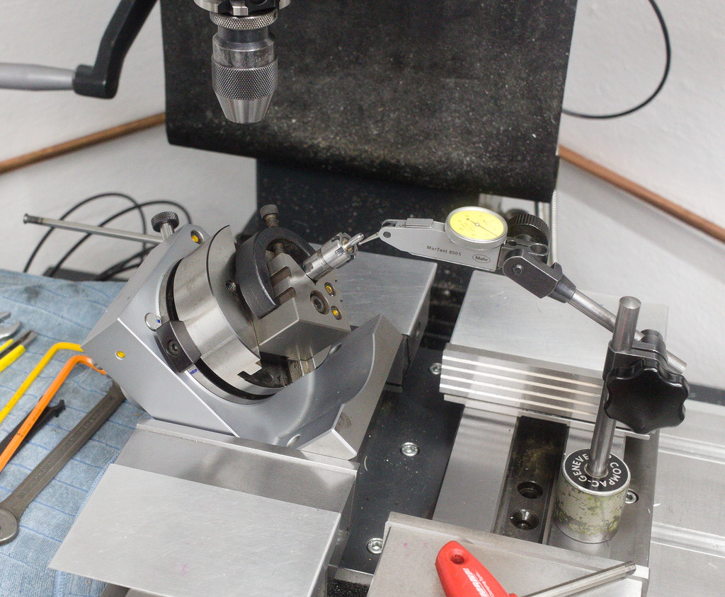
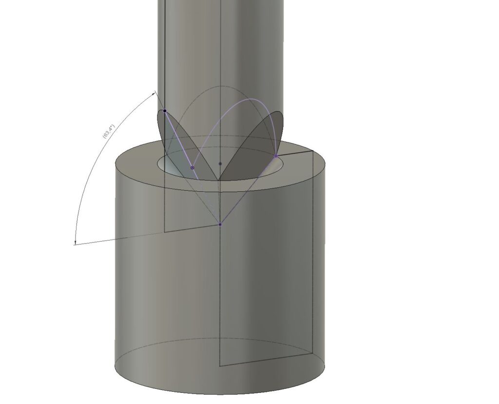
The angle the facets need to be ground can be determined in CAD – This example shows a setup for a 90° spotting angle – The Angle off the facets must be 63.4°
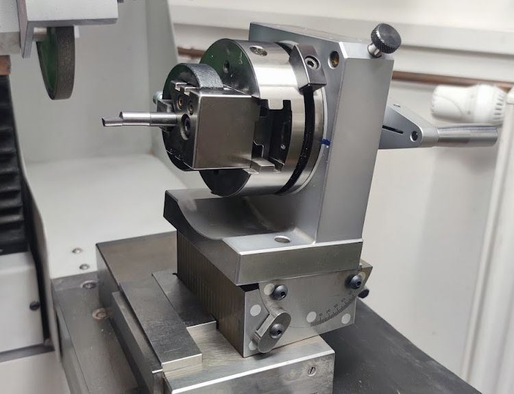
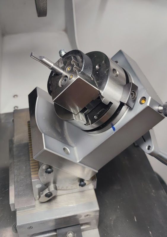
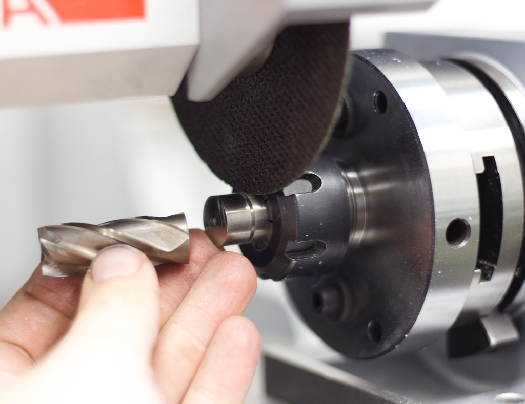
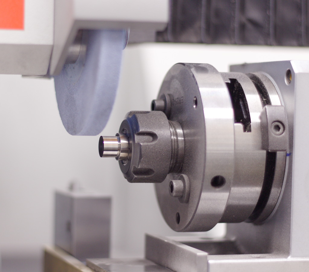
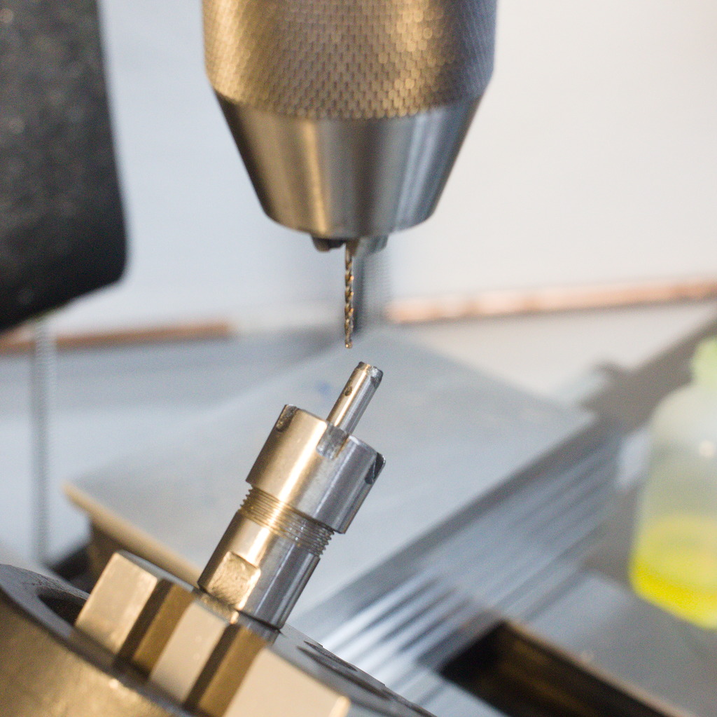
The following example has been ground on a Deckel S1 T&C grinder out of 3mm carbide stock aka the shanks of good quality endmills.
This very simple tool creates amazing, clean and round spot drills. The three cutting edges have a very negative cutting angle and are very robust, no matter what common material is machined.
Interestingly it works very badly when used dry, without any cutting fluid.
What I found works best is a small amount of cutting oil for steel/stainless steel/hardened steels and red metals like copper.
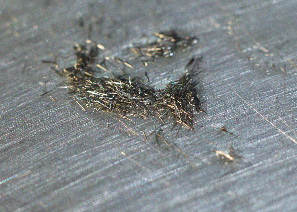
Used with oil it has a very nice and soft cutting action, creating fine, needle like chips:
When cutting aluminum, alcohol can be used as a cutting fluid, with the advantage of flashing off and leaving clean, dry workpieces.
Examples of Cutting:
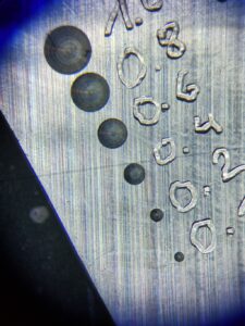
Spotting in aluminium AW5083 – The engraved numbers next to the spot drills represent the diameter of the spot:
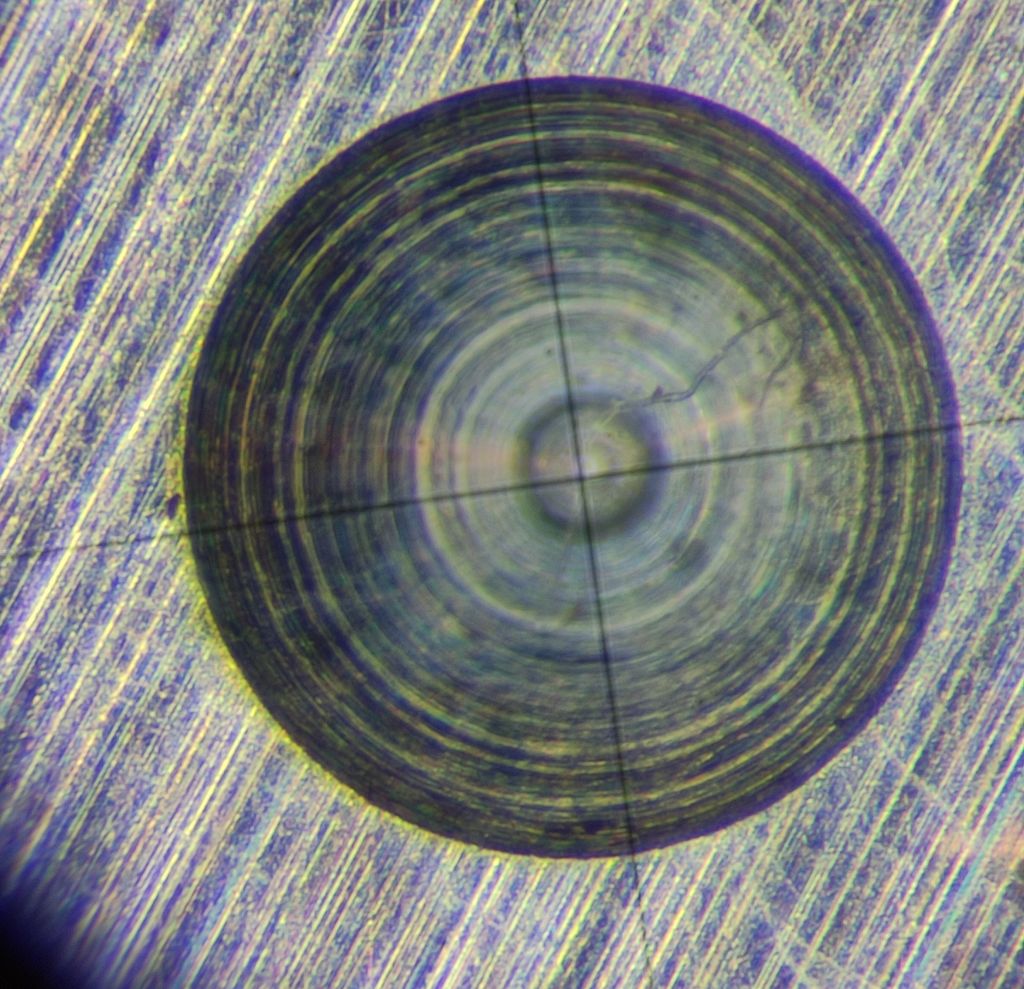
Magnified view:
0,4 / 0,2 / 0,1mm spotting diameter, left to right.
Since the drill is ground to a very small tip (As small as the grinding wheel and the grain size of the carbide allows)
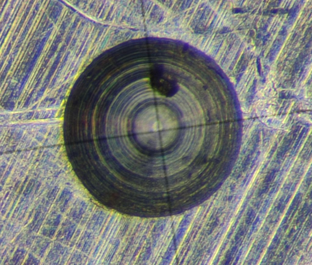
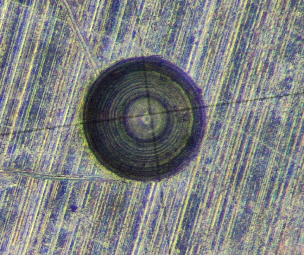
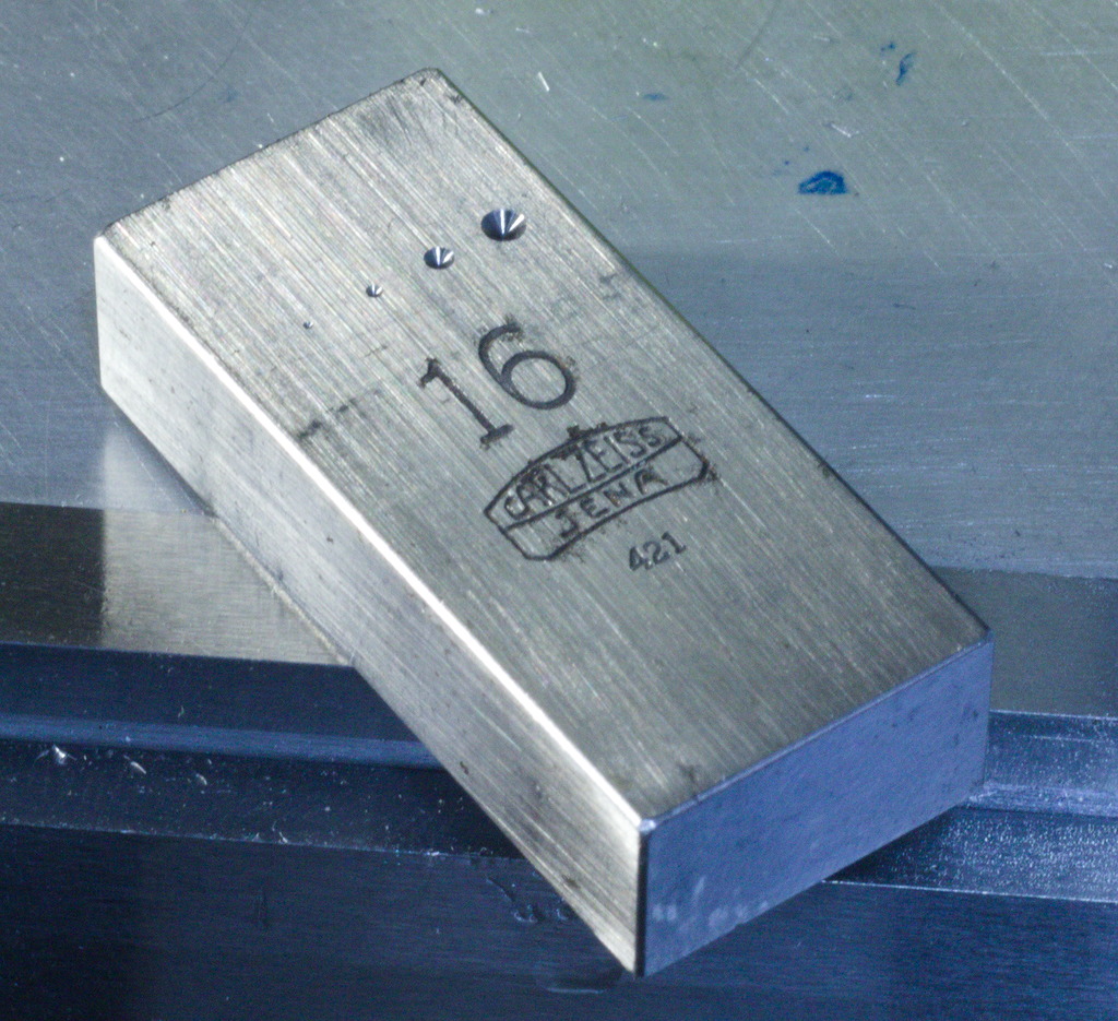
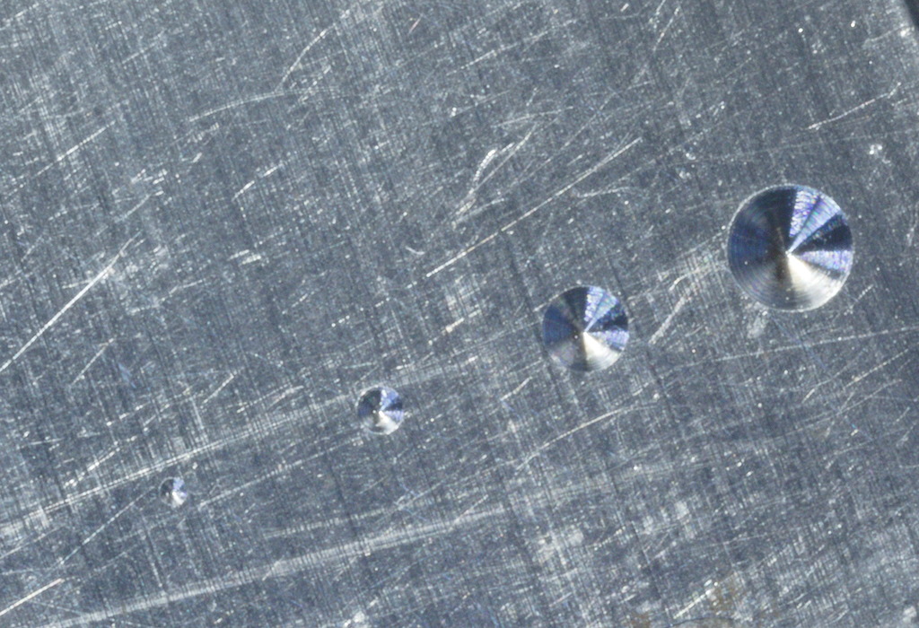
Spotting in hardened steel, an Old Carl Zeiss gage block:
Even in hardened steel, the pyramid drill leaves a very good center with minimal burr – Its amazing how well the unconventional geometry of the tool cuts almost all common materials.
Spott drilled stainless steel workpiece:
Conclusion?
This type of tool does not seem to be very well known, but it is sure worth giving it a try, if you have the capability of grinding them yourself.
Danny Rudolph mentioned these a few times in posts on Instagram, if you go back far enough in his posts.
Thank you, Danny, for making me aware of this tool.
One thing you, the reader, might ask: A 90° spot drill is problematic for carbide drills, since the tip angles don’t match up, right?
That’s at least the common conception, but with micro drilling it seems to be less of a problem. Getting a center/spot that’s small enough for a micro drill is already hard enough and on such a small scale there’s more effects at play – The drill might vibrate for a very short period when touching the spot before calming down and actual cutting. This can be observed with a video microscope very well.
The issue is, with a larger tip angle, this style of tool starts to cut less well, since the included angle between the clearance and the top rake surface get bigger and bigger therefore more and more negative, requiring bigger force to make the tool cut well.
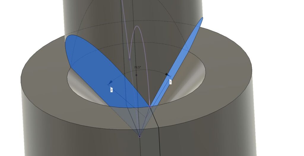
90° Spotting angle: 78.5° included angle
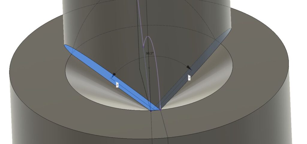
118° Spotting angle: 96.5°included angle
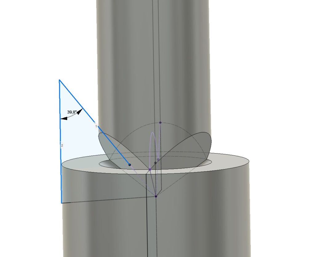
If you want to give a 118° version a try, here is the angle to be ground onto the pyramid:
Despite that, give them a try, I think you will not be disappointed – It has become one of my absolute favorite tools – Simple and very reliable.
There will be a moment in time in almost every lathe owners’ career when the desire for a tool post grinder starts to grow.
I have a strong opinion on tool post grinders, and it’s not a good one.
The idea:
Creating higher precision parts, possibly out of hardened materials
The reality:
Grinding is not an inherent more precise process
Grinding adds another layer of complexity
Lathes are not designed to be a very good ID/OD grinder
Tool post grinders are often quite crude devices. Very heavy and cumbersome to setup, often with belt drives that tend to add vibrations, motors sitting on top of a large stack up that add vibrations to the entire system
There are exceptions of course – Some materials just can not be cut with carbide/diamond or CBN inserts in a cost-effective manner. Ceramics and Carbide can be such a exception, also they have some utility when working with hard chrome plated items like hydraulic rods.
ID work in hardened steels or ceramic/carbides can be a case where grinding on the lathe is a viable solution, if no other machine is available.
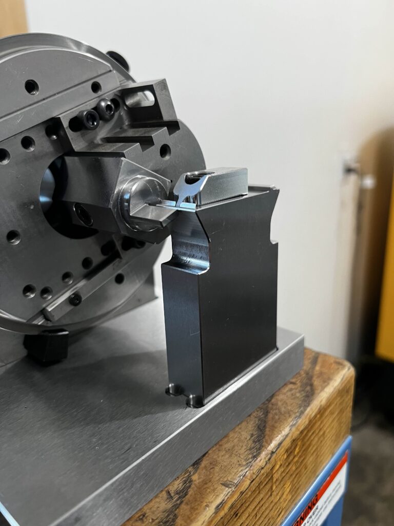
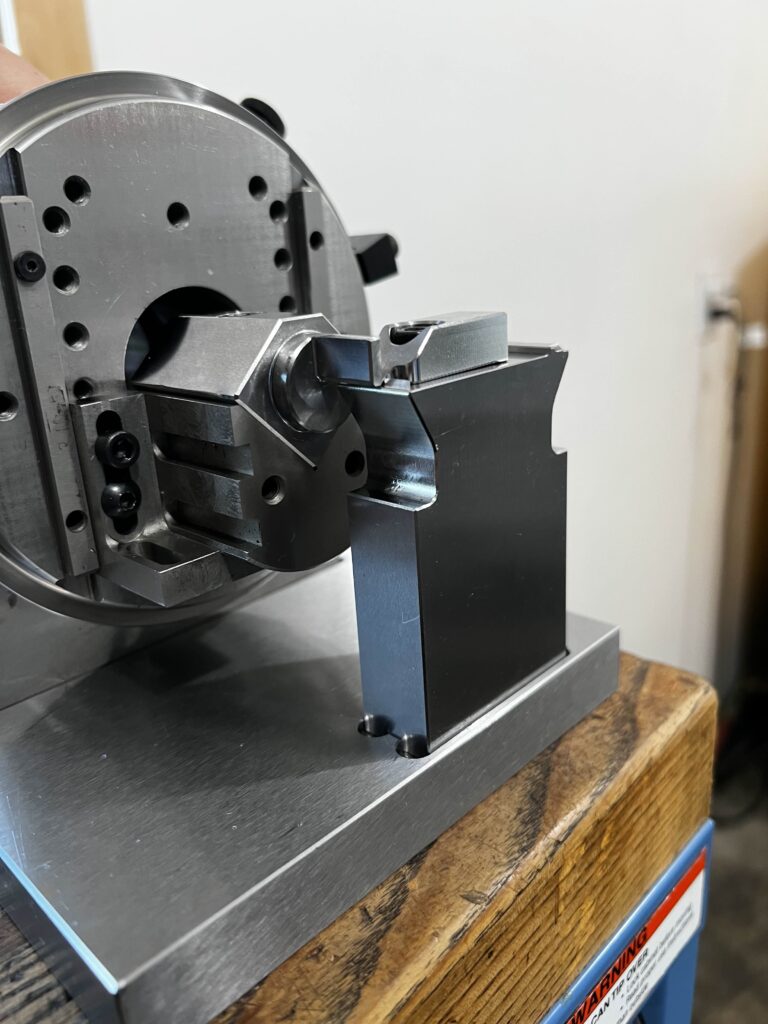
But even then, it’s a good idea to keep the actual grinding done on the lathe to a minimum – I had to make some carbide bushings, to keep grinding to a minimum, I had the ID bore wire EDM cut to almost finished size, the OD of the stock was chosen to be the final dimension, and the length was ground on the surface grinder.
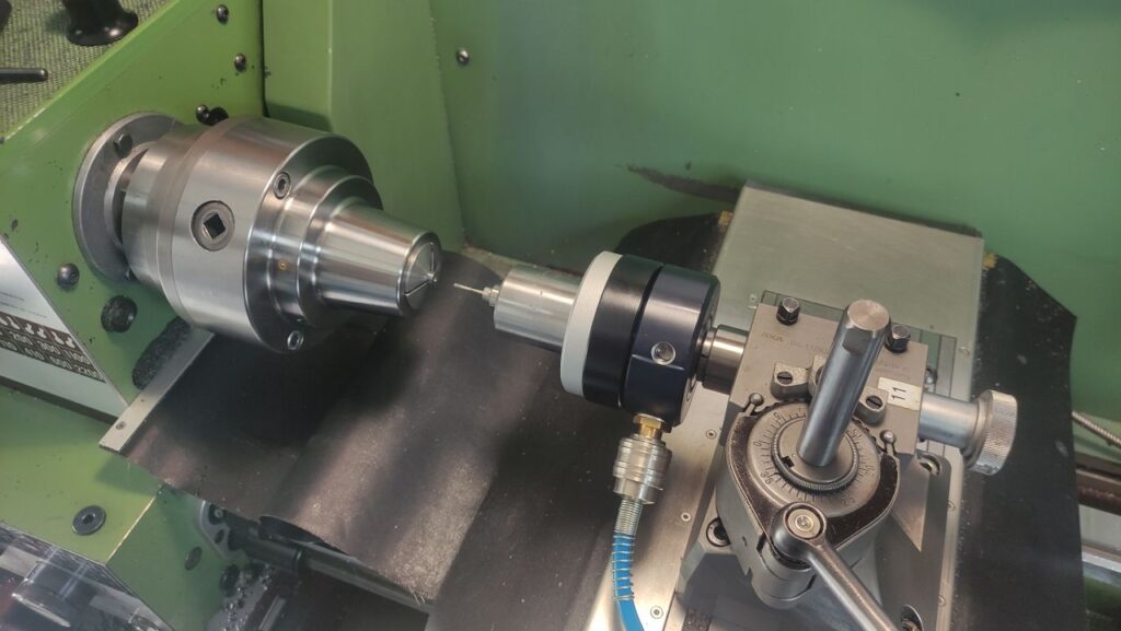
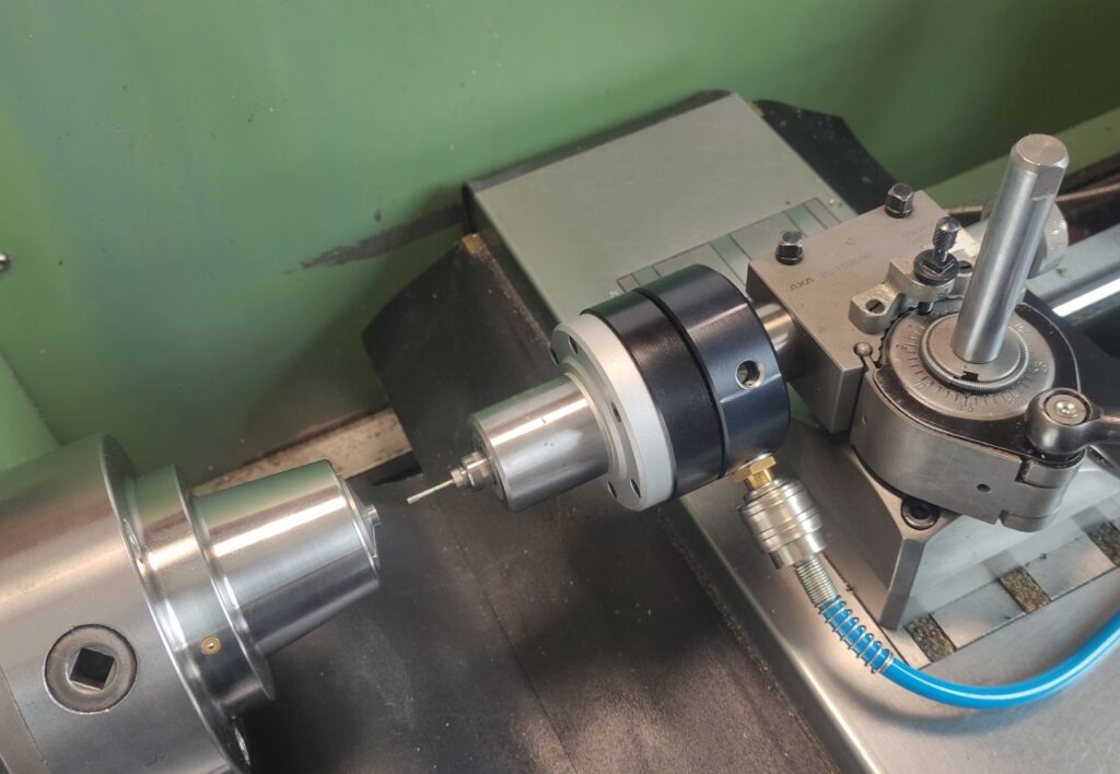
The actual grinding on the lathe was performed with a high-speed air driven spindle, held in a boring bar holder. This setup has some advantages over a classic tool post grinder, since it’s easy to setup.
Most standard belt driven tool post grinders are too big to mount into a quick change tool post, they require to be bolted to the compound directly.
Centering and locating features on either a CNC or manual milling machine is a very important step. The industry provides us with a wonderful selection of tools for this purpose, edge finders, mechanical 3d probes all the way up to electronic probes that talk to the CNC controller.
There are tools and techniques beyond of the here shown, like centering microscopes that let you pick features visually, the very oldschool wiggler or even a simple dowel pin in a collet.
But the ones here shown are the more common that I have to say something about.
Edge Finder
The simple edge finder is a tool that I like very much – It is very affordable and reliable yet delivering a high degree of precision when picking up workpiece edges.
The design of the tool does not necessitate perfect runout, the work just as well, when you put them into a drill chuck.
Mechanical 3d Probe
The least favorite Solution for me is the mechanical 3d probe – They have a surprising high actuation force that is not equal in all directions, they are highly depending on their runout being set correct, they need a dedicated toolholder (That’s more a nuisance on a manual mill than on a cnc) and are overall not very confidence instilling to me.
These types of probes also require a fair amount of clearance between the spindle and the work.
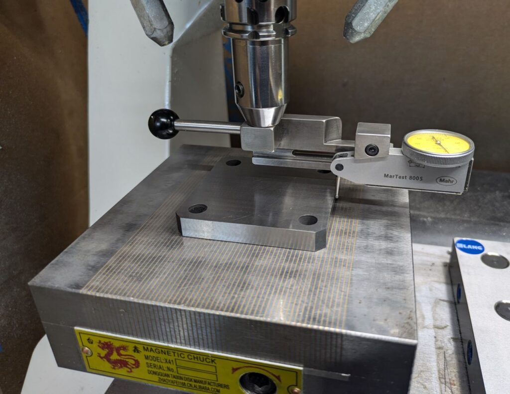
Dial test indicator
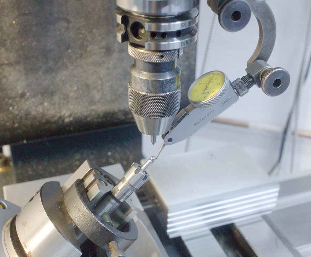
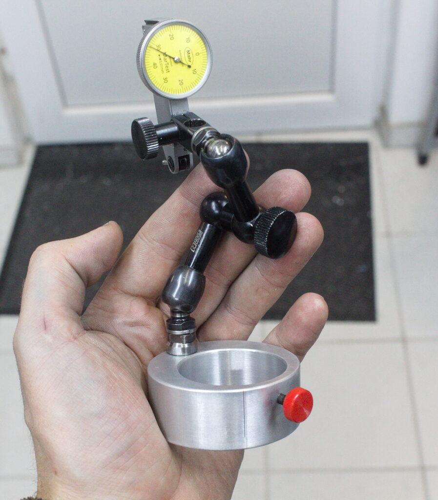
My favorite solution is a dial test indicator that is in some way mounted to the spindle of the machine and has some adjustability built into it.
This can either be a flexible arm – like what is used on a magnetic indicator stand – Held in the spindle or clamped to the spindle/toolholder.
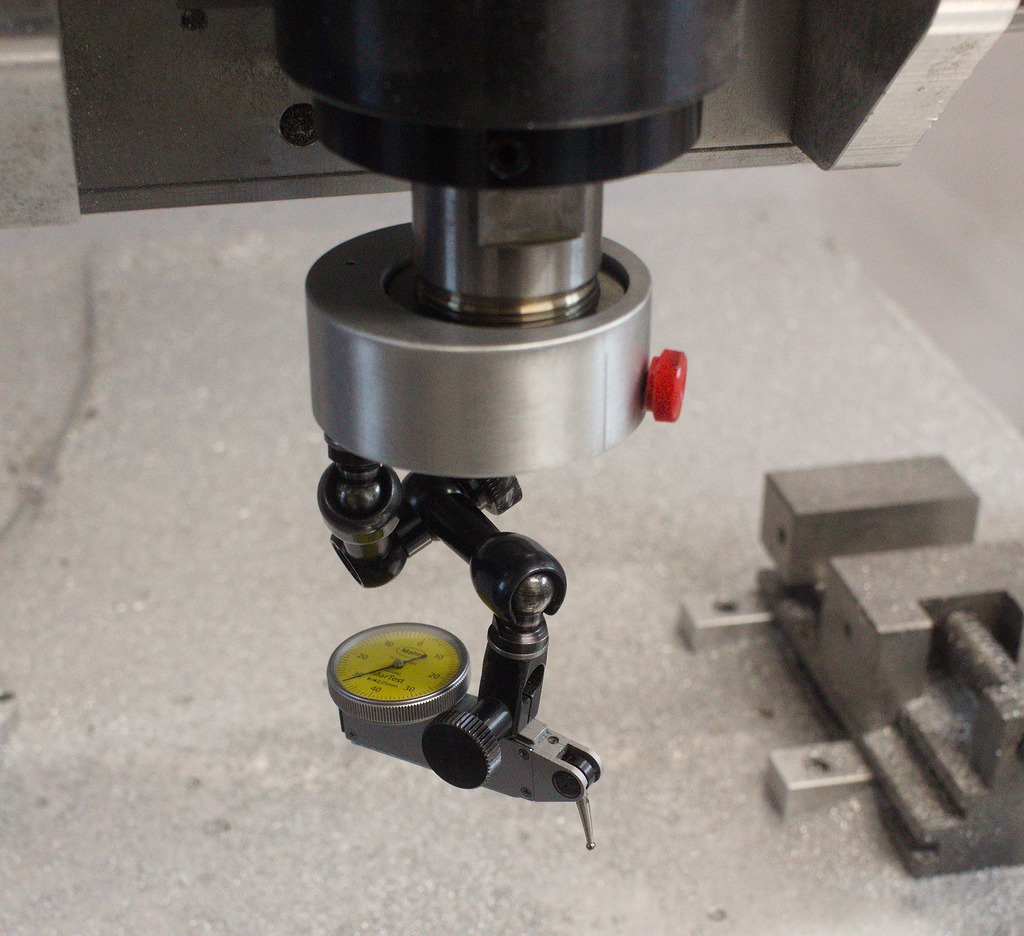
This is an example of a flex arm mount that is clamped to the ER25 collet nut of a high-speed spindle.
Holding them in a drill/collet chuck is also an option:
These holders give a great range of freedom, but that’s also a drawback, since its quite time consuming to align the probe tip in a meaningful way.
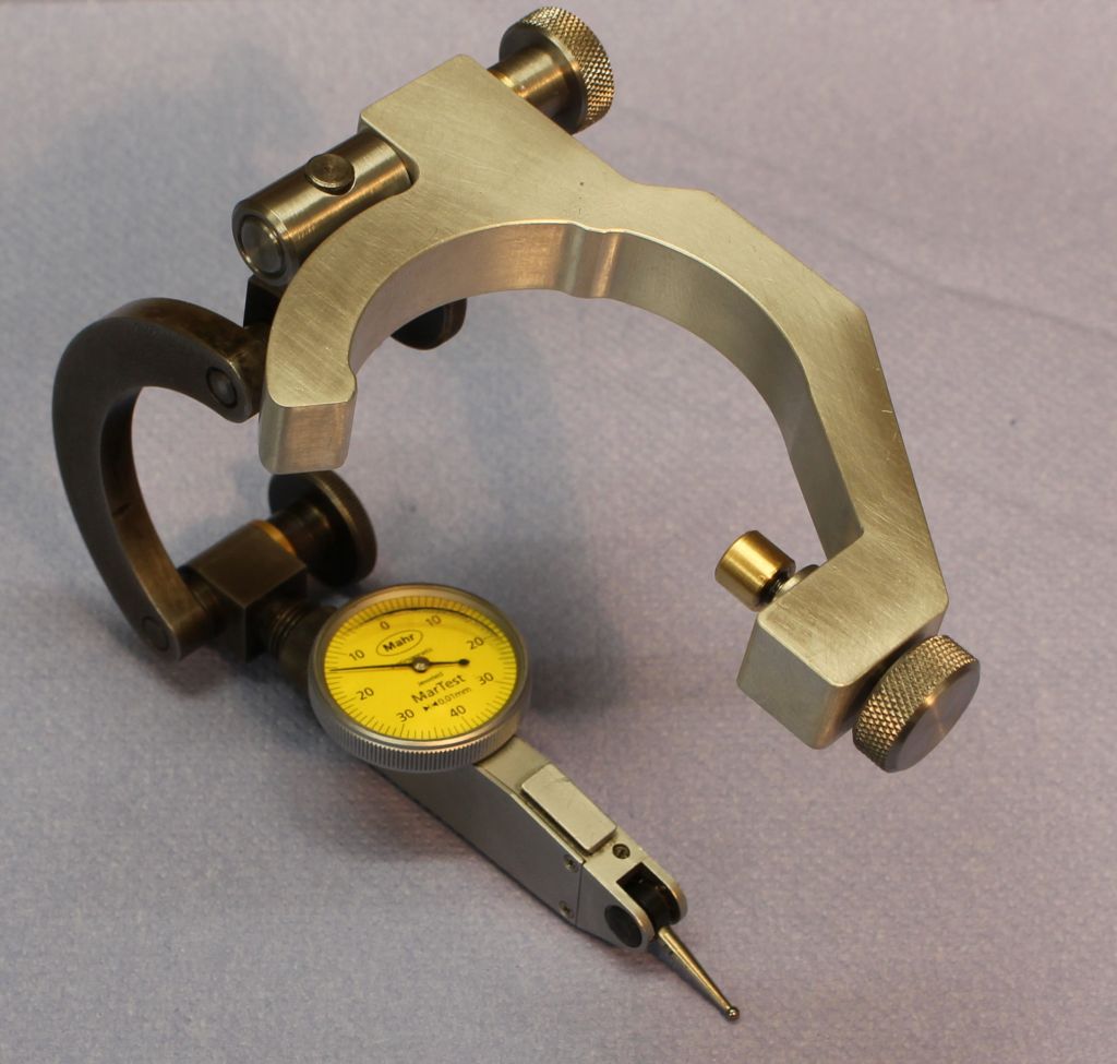
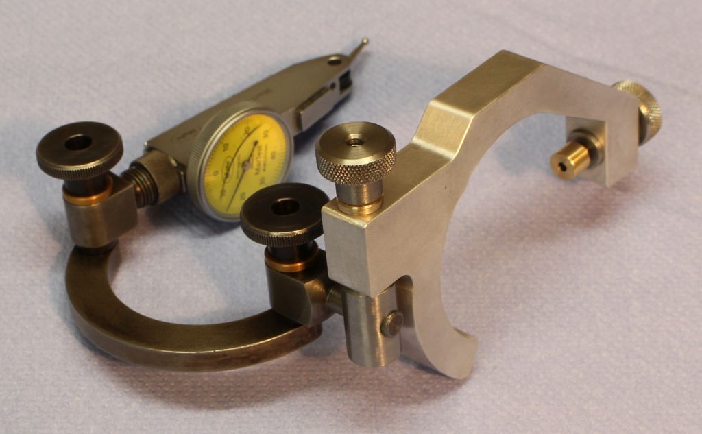
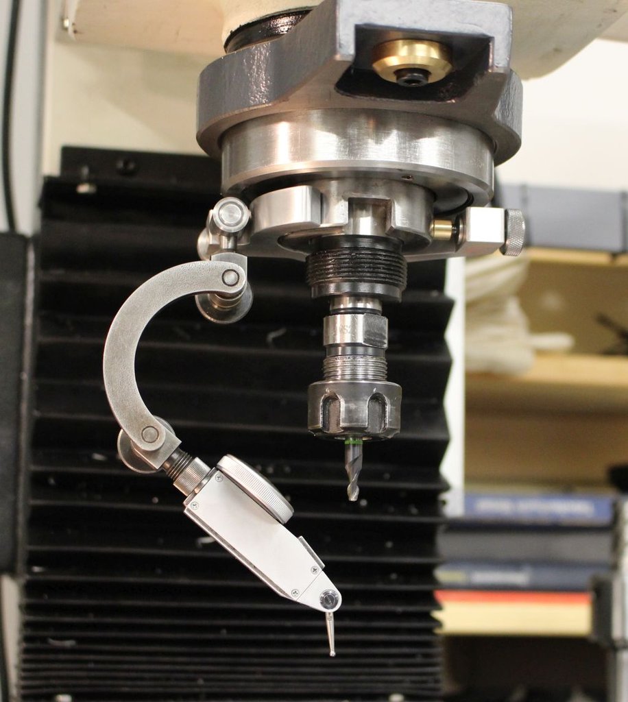
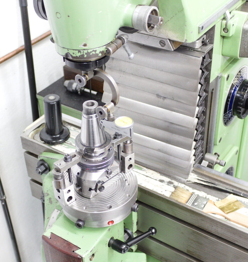
Personally, I prefer a holder that has less freedom of motion, like the very popular halfmoon shaped holders that can also be held in a toolholder or clamped to the spindle/toolholder with an additional clamp.
These can either be purchased commercially or make for a neat little shop project. The one shown here was built in-house, a set of drawings for the half-moon holder is available in the files section.
Held on a milling machine spindle vs. held directly in a collet:
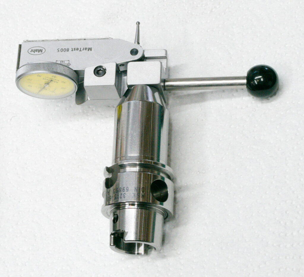
For certain types of machines, like CNC routers height clearance is a real concern – None of the commercial options are very satisfying in that regard. That’s why I came up with the following design that’s extremely low profile and has the necessary adjustability to line the stylus up with the center of rotation built into it.
The set of drawings for this holder can be found in the Files section of this blog.
Hi! Stefan here – You might know me as a that long haired dude on Youtube creating videos related to machining. With this blog I will try to create a spot on the internet that is not created by AI, Language models or other artificial means.