There’s a bit of confusion with new owners about Deckel milling machines and the tooling.
In short, the machines use a 40 taper with an external S20x2 buttress thread.
People new to these machines seem to be concerned about the availability of that tooling, and let me tell you: It is not an issue.
Used Deckel spindle tooling is plentiful and affordable for the most part, and modern tooling can be adapted very easily.
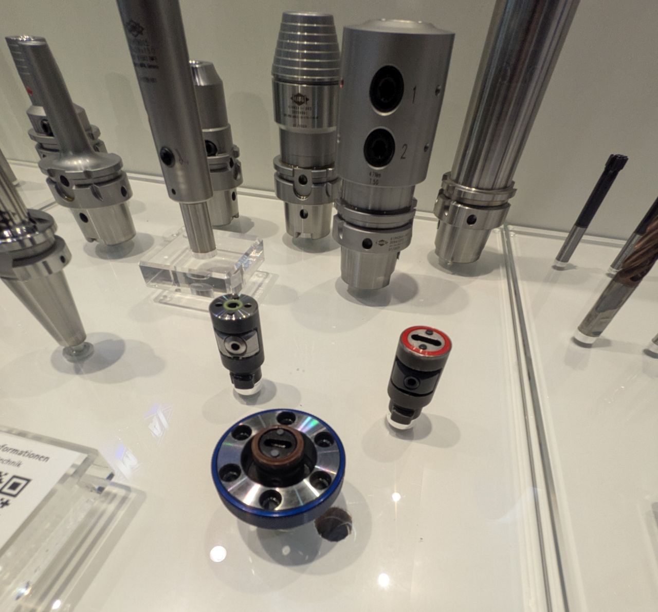
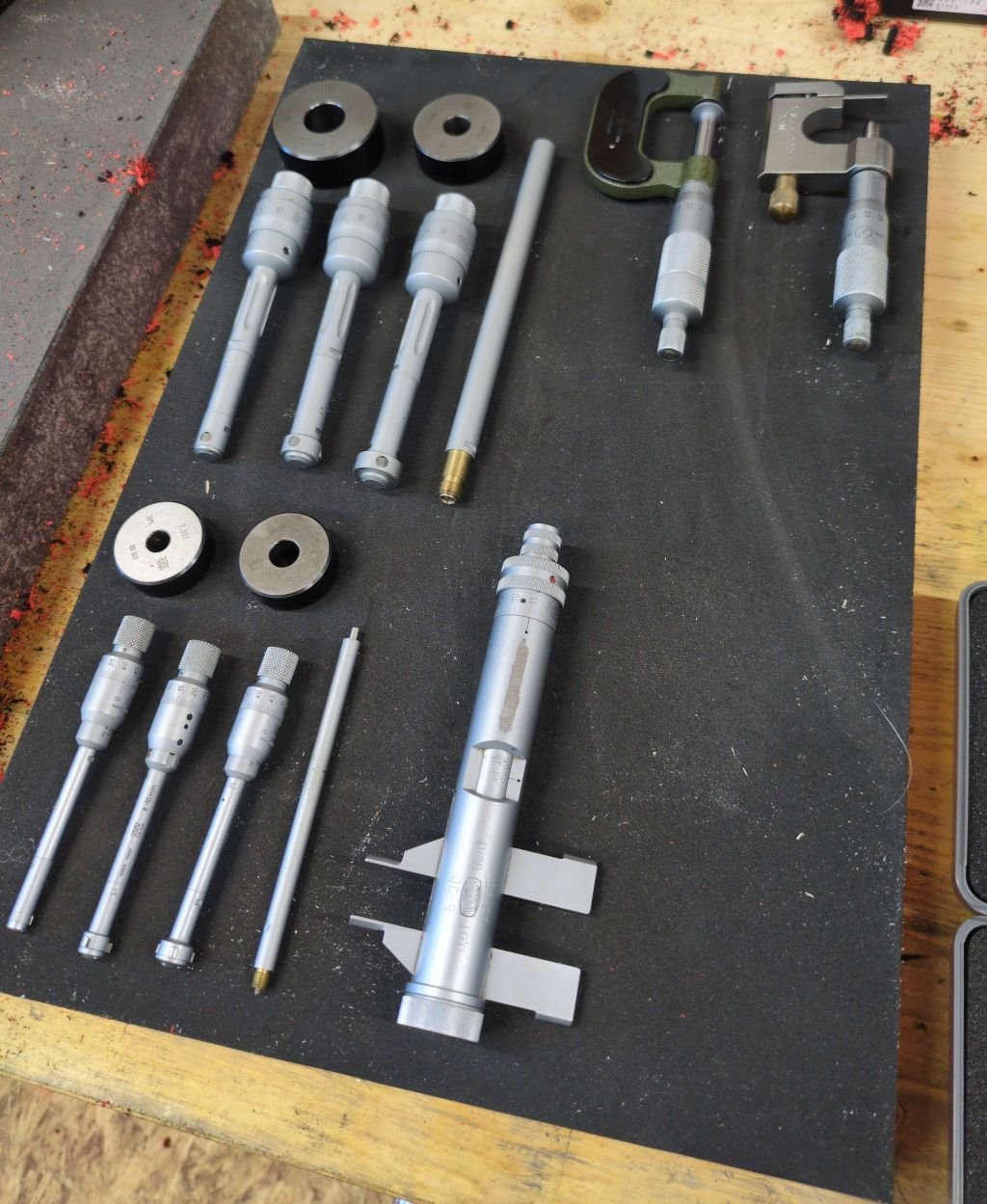
Let me start with an overview:
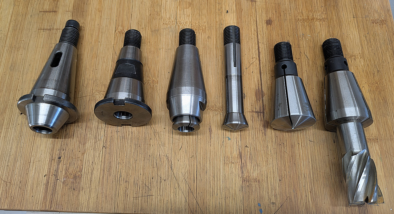
From Left to Right:
- Standard Morse taper adapter (Available in MT1 to MT3), to be used with tanged tooling like drills or with a screw to hold end mills or a boring head with a taper shank in the adapter.
- Short Morse taper adapter (Available in MT1 to MT3) with internal screw – Only to be used with tooling that has a Morse taper shank with drawbar thread. I use it in conclusion with my Wohlhaupter UPA1 boring head.
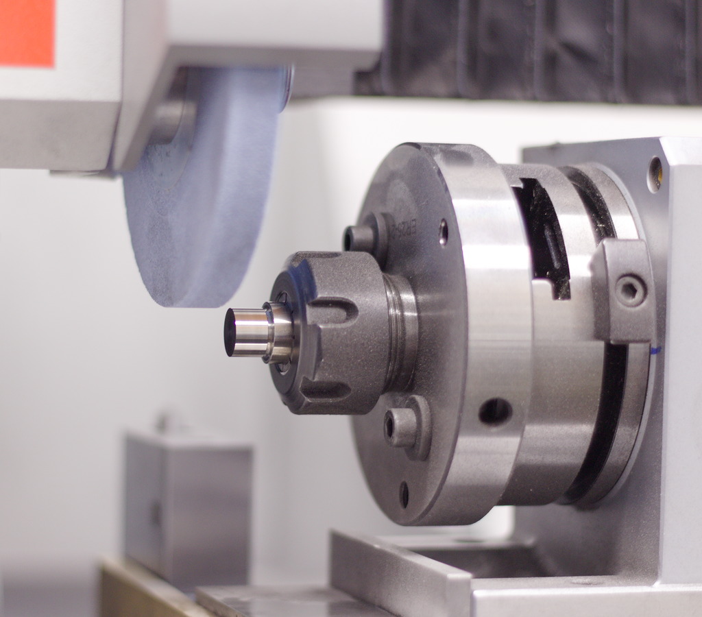
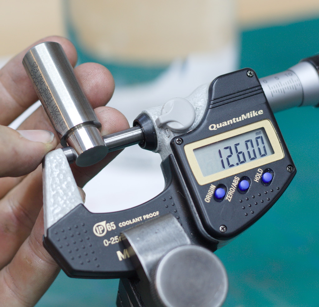
- Reducer sleeve for 355E collets and an individual 355E collet. This is in my opinion the most universal and useful combination. The collets are available in 0.5mm increments and don’t add much z-height. They can hold all tools with a cylindrical shank. Heavy roughing leads to tooling getting pulled out of the collet.
- 40 taper collet – These are very heavy-duty collets, available in 1mm increments, but mostly used for larger endmills – the larger sizes have a thread that interfaces with (these days very obsolete) the thread on end mill shanks, allowing very heavy roughing without getting tools pulled out of the collet.
These are the main options that Deckel supplied and offered for their machines. In my opinion, still a very viable loadout.
If you buy a Deckel milling machine, these are the essentials to look for. Used machines often have at least a basic assortment of these holders, sleeves and collets.
Additional information
„Modern“ 40 Taper tooling
If you are looking for an option to use modern 40 taper tooling in a Deckel milling machine, that is not a problem at all.
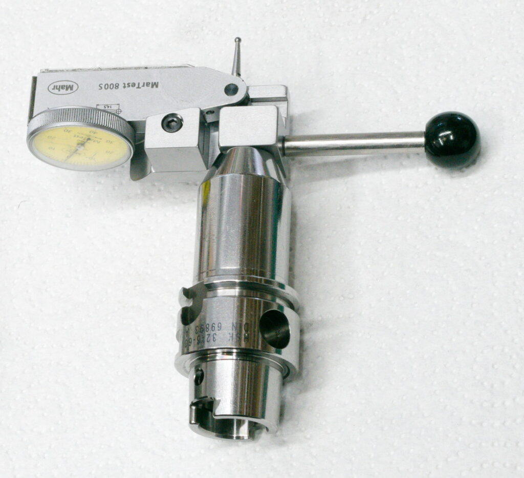
Regular DIN69871 or now ISO7388-1 tooling in combination with a readily available S20x2 pull stud creates a combination that can be used in Deckel milling machine spindles without any further modifications – No matter if we talk horizontal or vertical spindle, high speed or boring spindle or the indexing head.
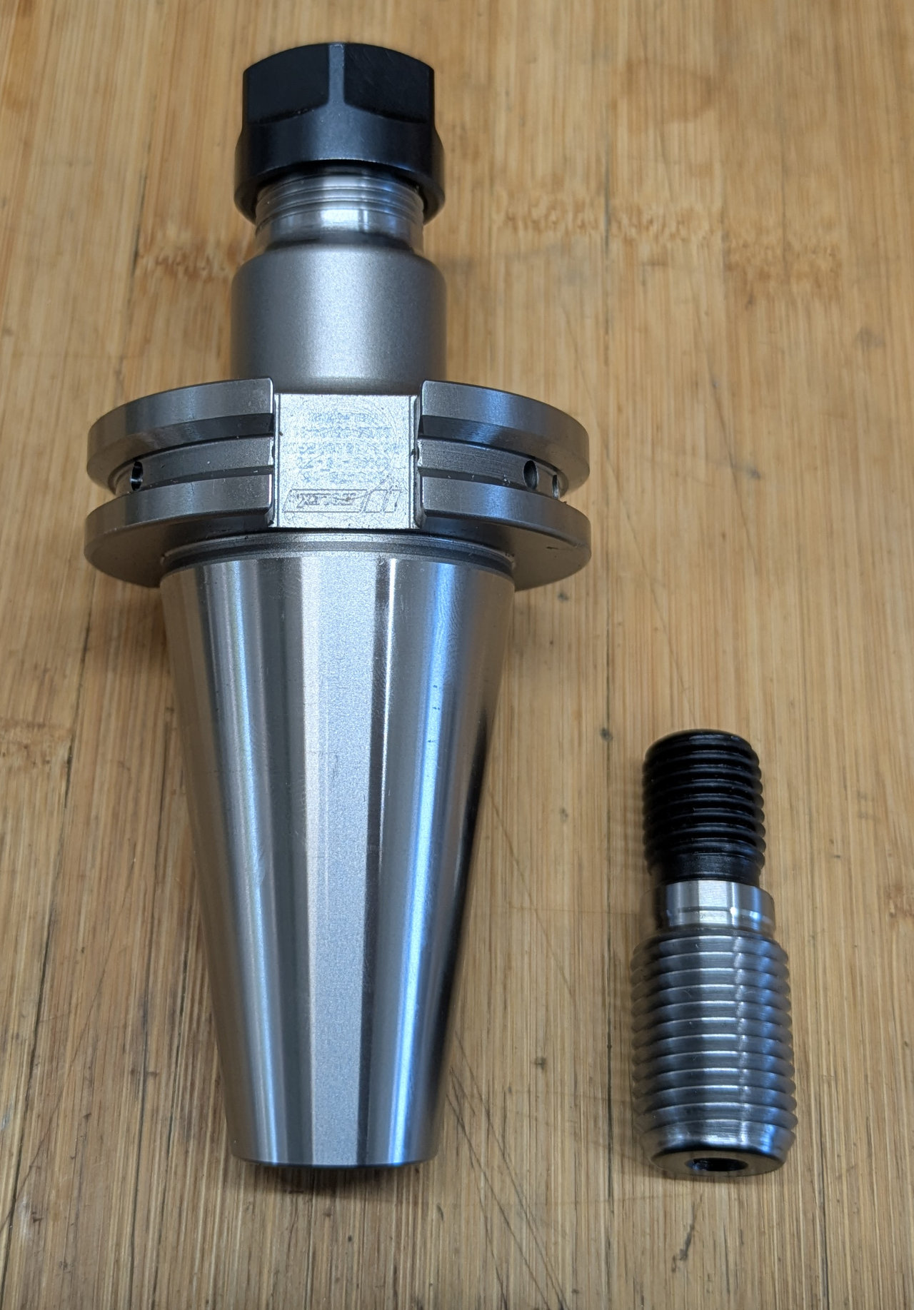
Regular commercial DIN69871 ER16 collet chuck and a S20x2 pull stud.
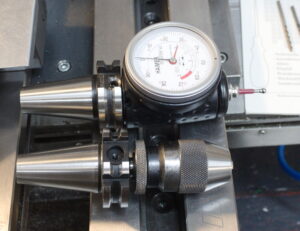
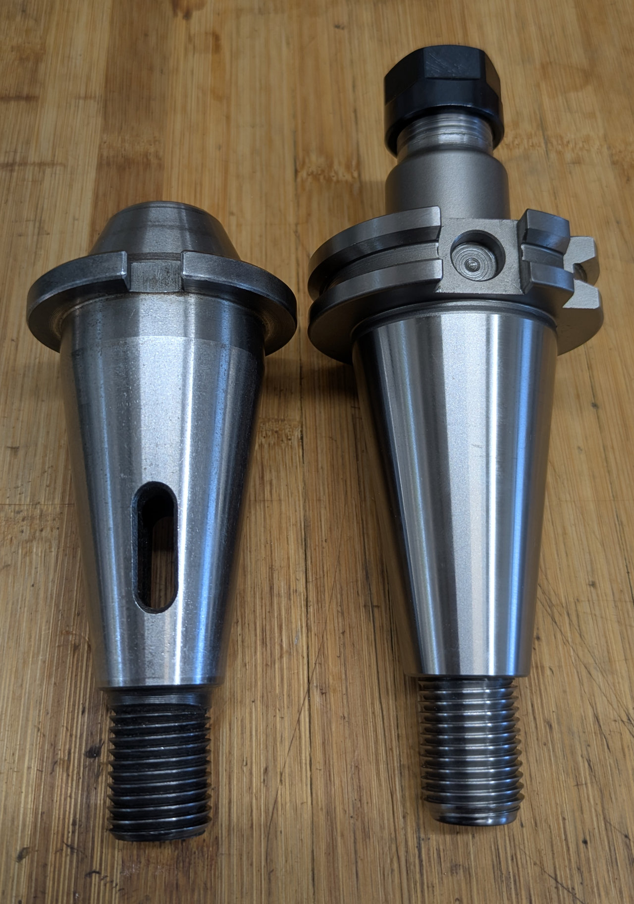
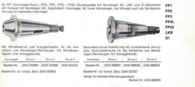
MT1-MT3 reducer sleeves
The short and standard profile reducer sleeves have overlapping uses, but the short one cannot hold tooling with a tang, like taper shank drill bits.
But it is a bit shorter and has an integral screw to hold taper tooling like a boring head securely in place. Note the length difference.
The standard sleeve can be used with a screw or without.
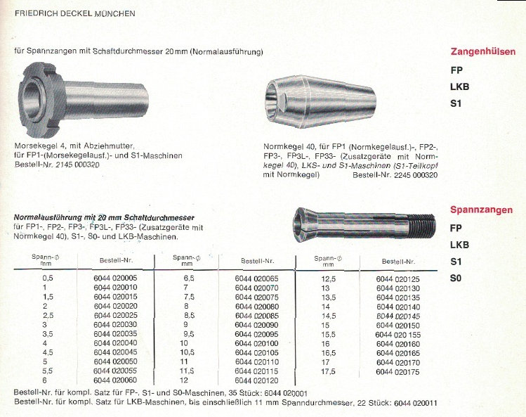
Scan from the Deckel Accessoires catalogue:
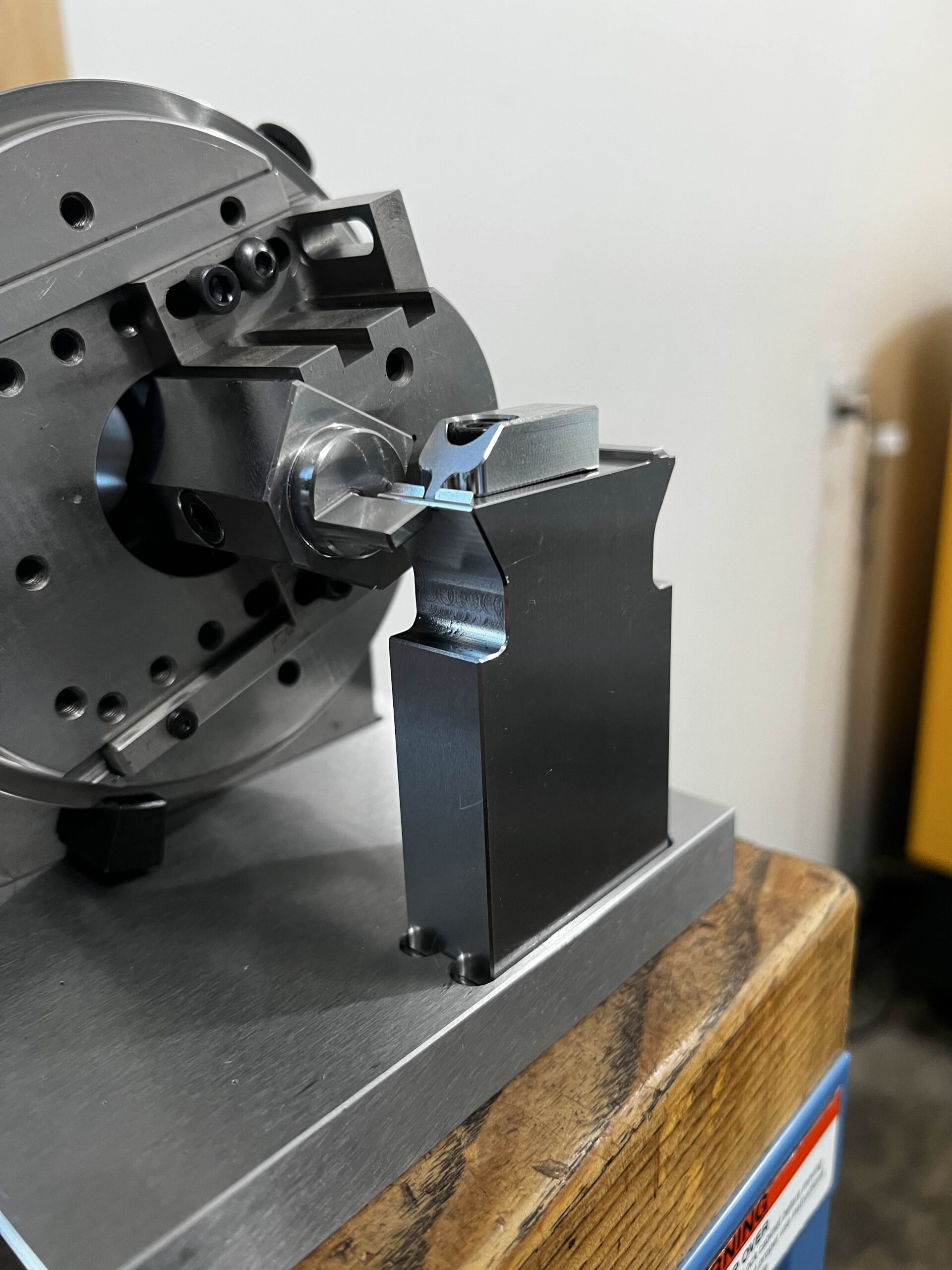
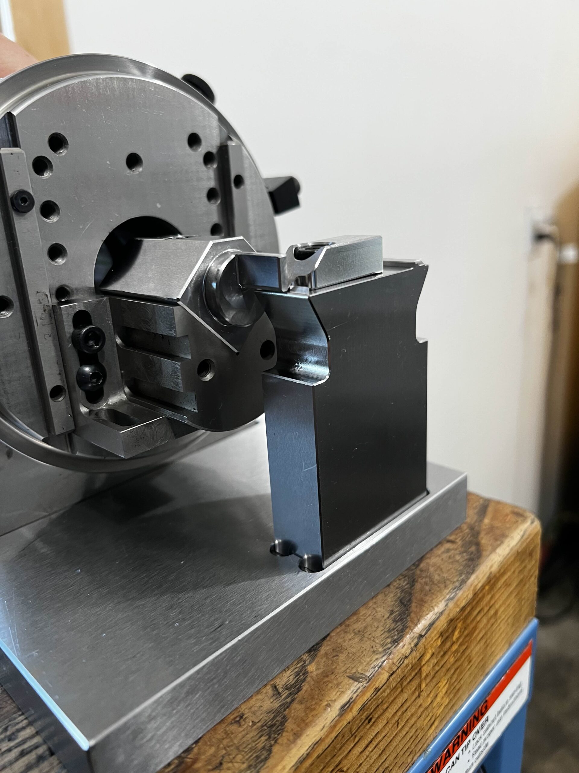
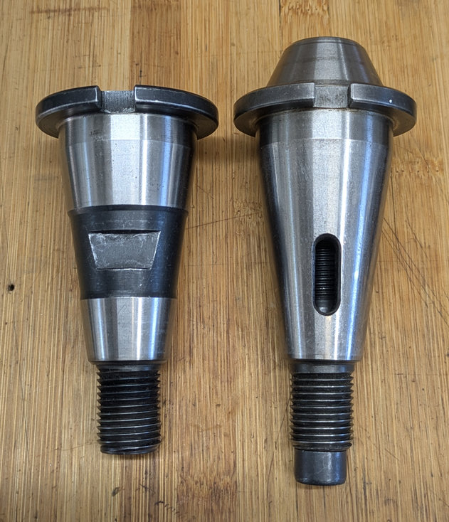
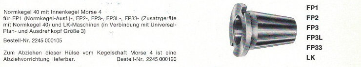
Open MT4 reducer sleeve
This was not shown in the overview picture, but it is still very useful and important if you want to use old MT4 tooling in a 40-taper Deckel mill.
The short MT4 sleeve has no drawbar threads on its own; it relies on the MT4 tool’s drawbar thread.
To be used in a Deckel mill, the original MT4 needs to be shortened a bit, and a S20x2 pull stud needs to be screwed into the M16 drawbar thread of the MT4 tool.
This is a decent way to continue using older tooling.
The sleeve can only be removed with a two-arm gear puller.
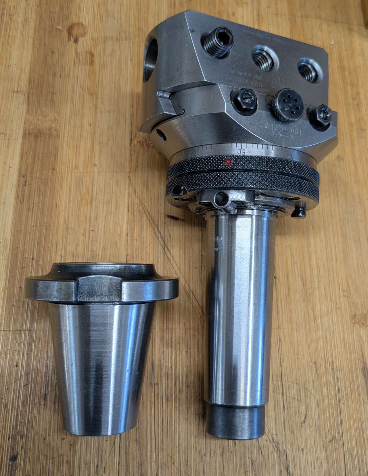
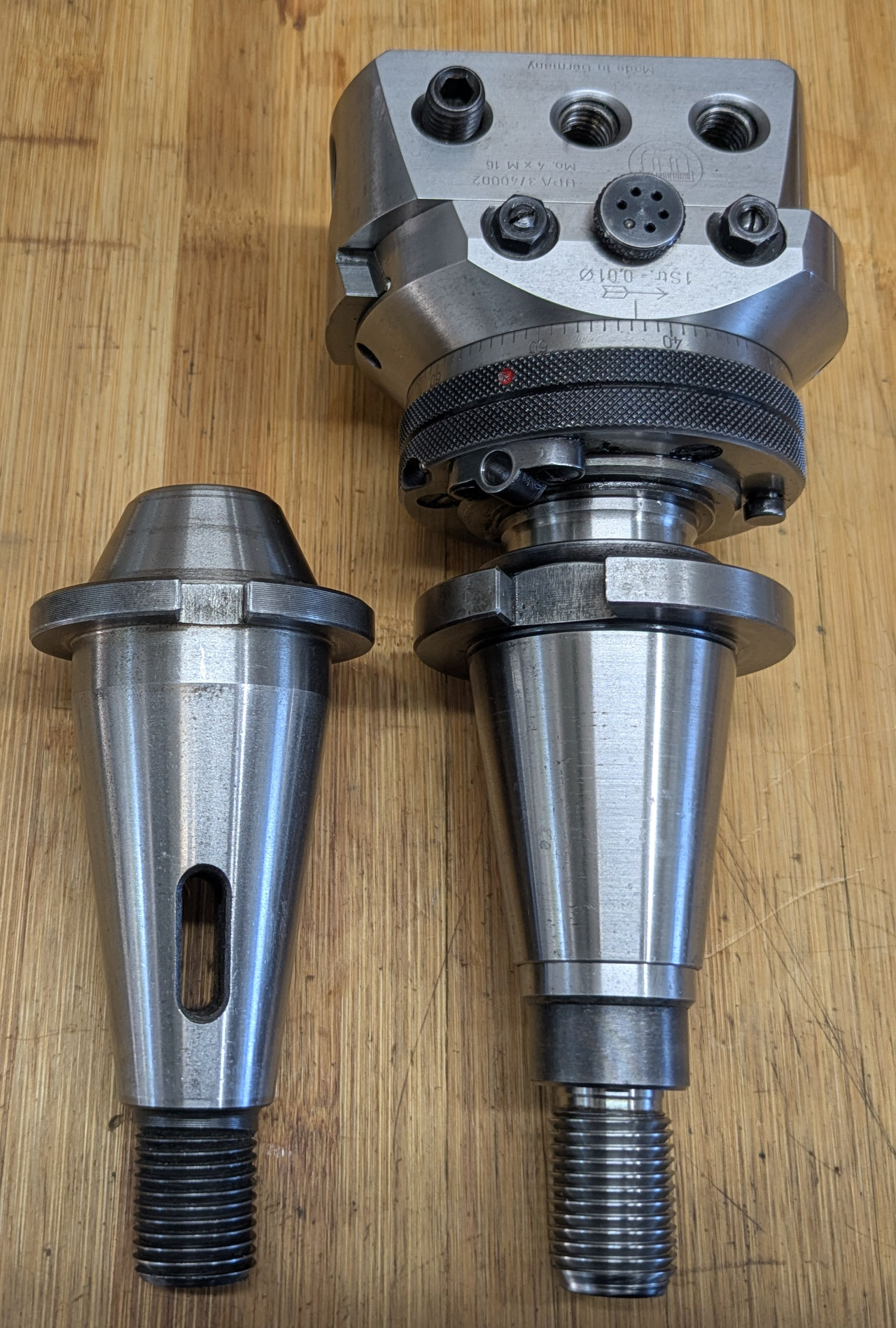
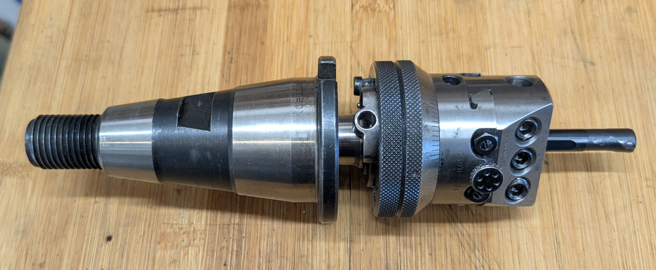
Here shown with my Wohlhaupter UPA3, next to the MT2 reducer sleeve.
Scan from the Deckel Accessoires catalogue:
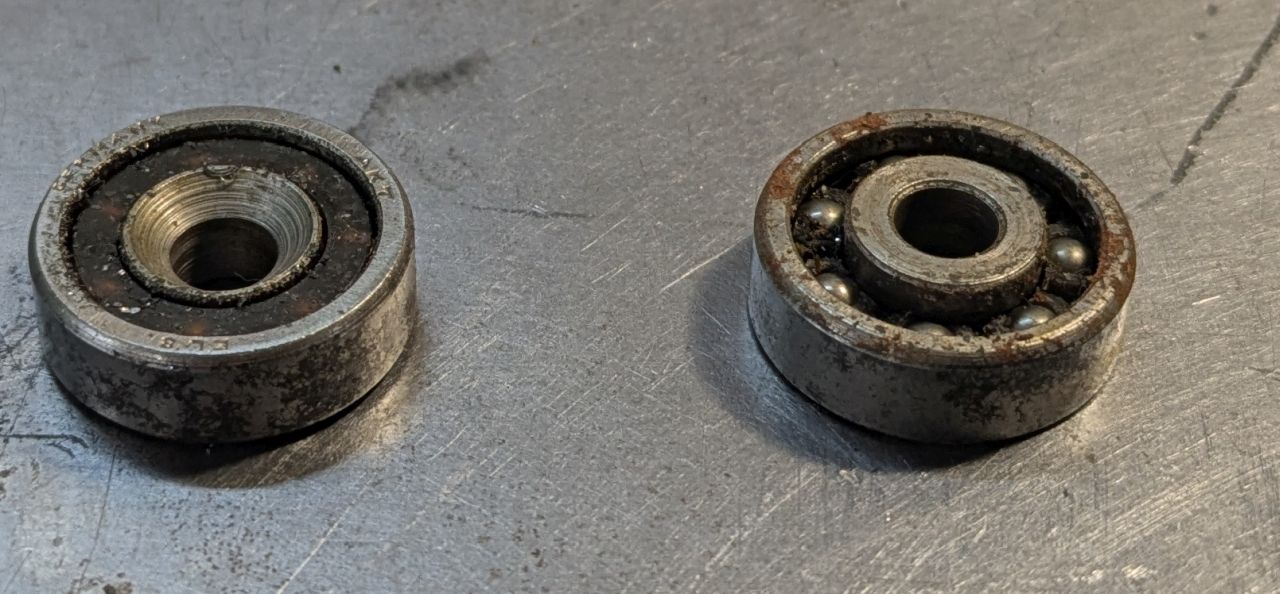
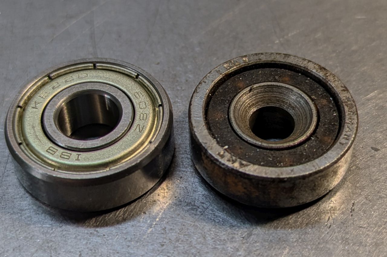
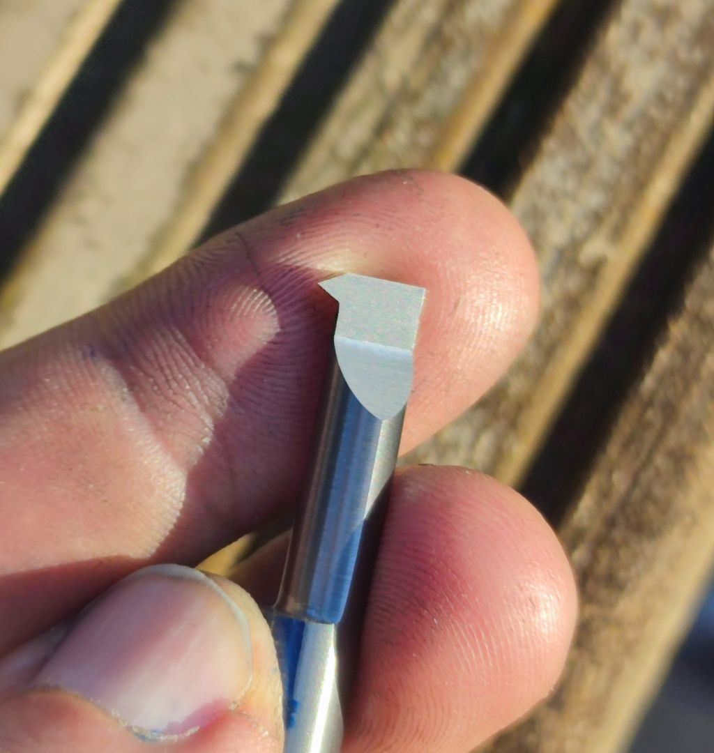
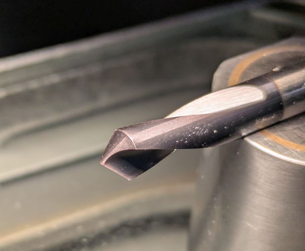
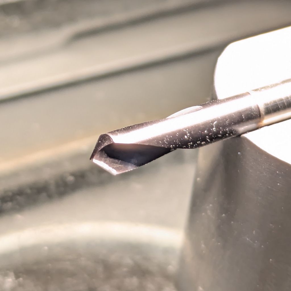
40 taper collet
The large collets where also marketed as „DUBLOK“ collets.
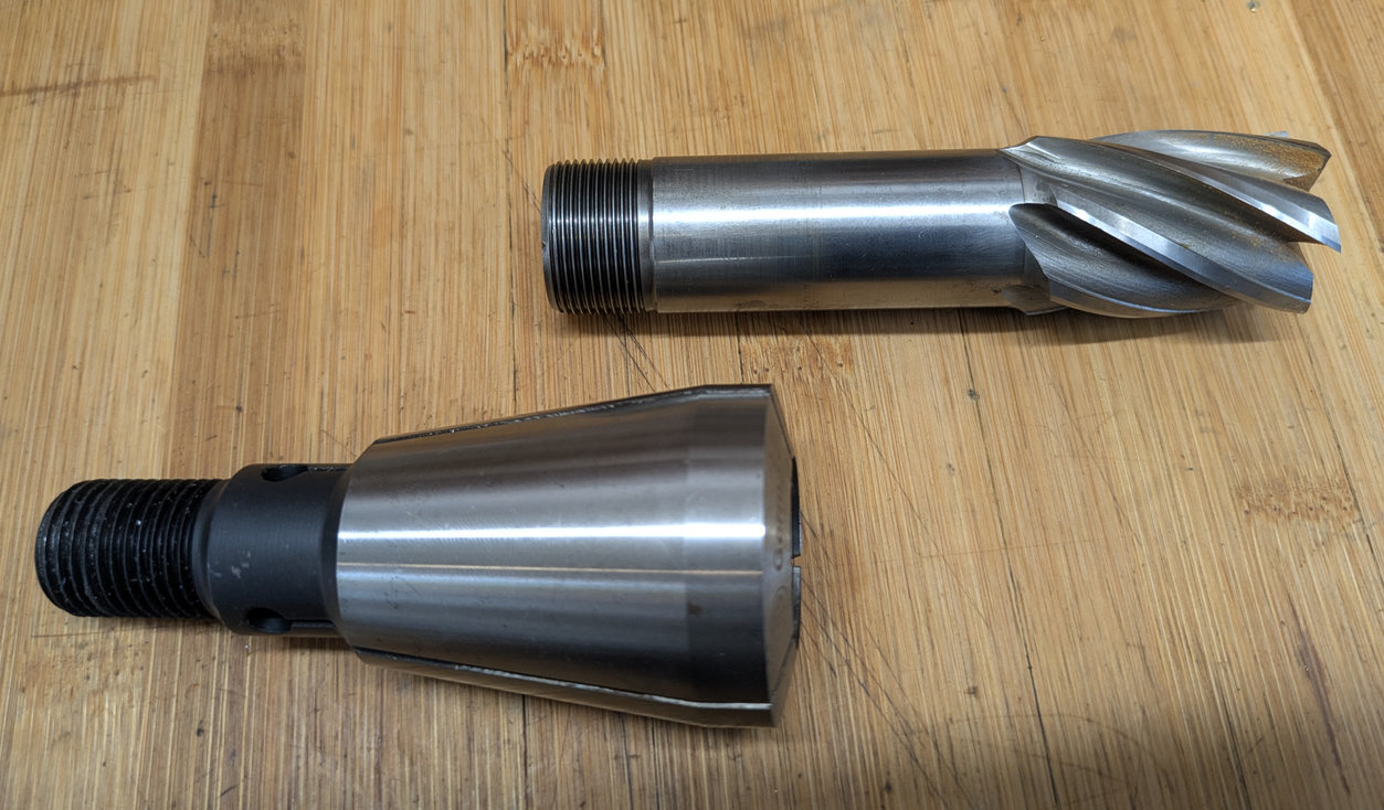
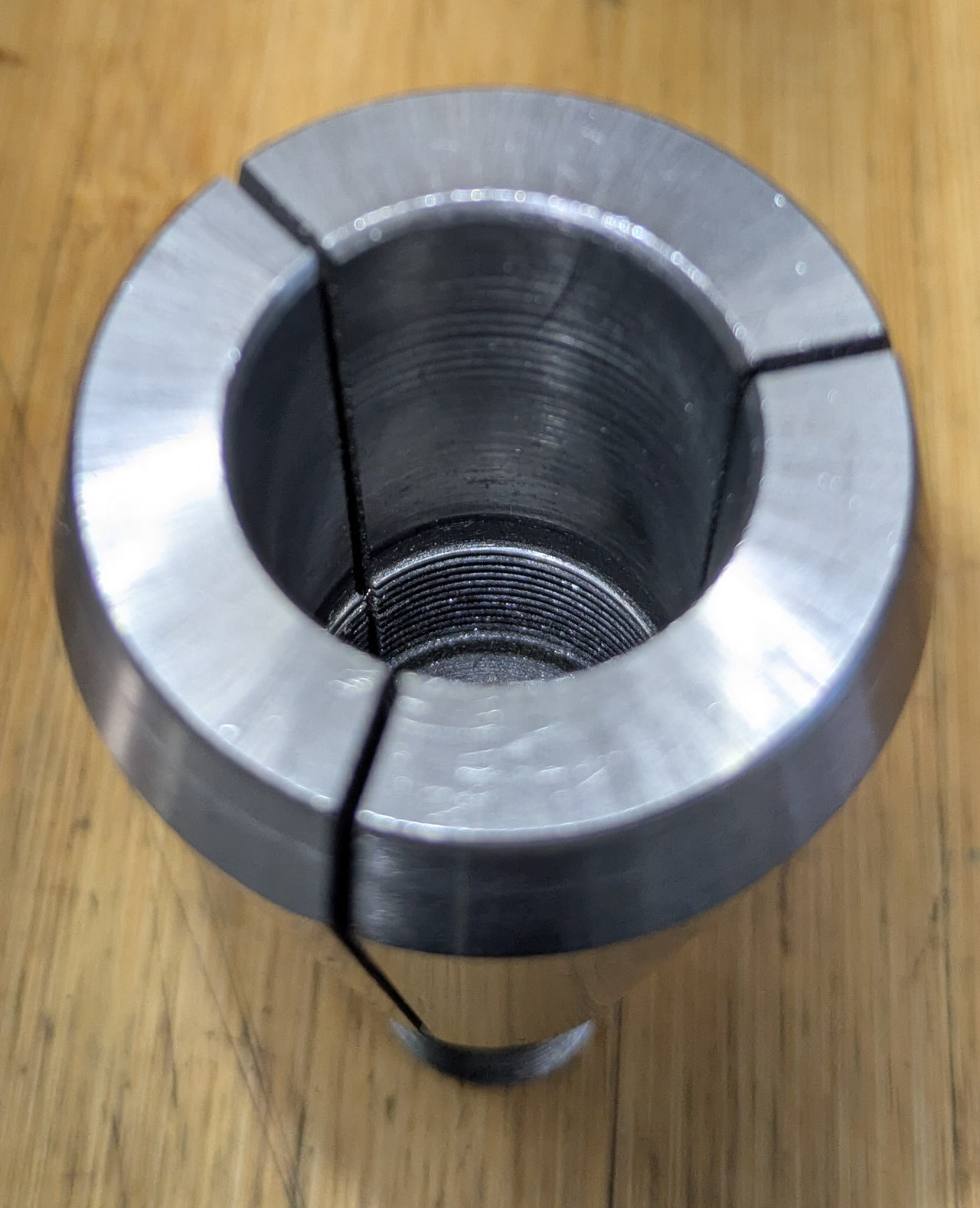
In the right picture the thread that interfaces with the end mill can be seen behind the cylindrical gripping section of the collet.
Scan from the Deckel Accessoires catalogue:
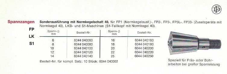
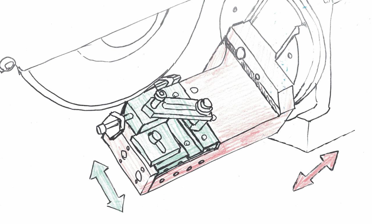
Old advertisement for „DUBLOK“ collets out of the PFEIFFER Catalogue
(The red marked picture shows the collets in my photo.)
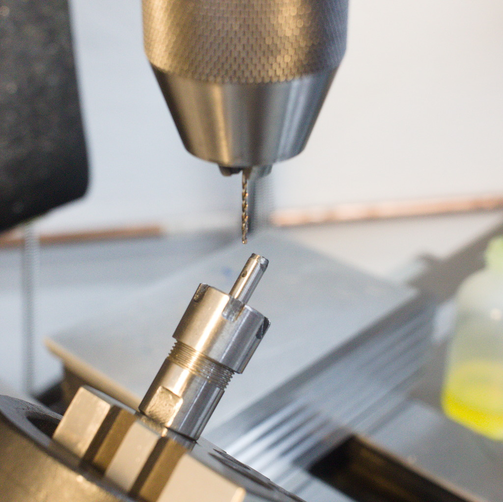
Short drill chuck option
In all the years I used Deckel milling machines, I always had a small 6.5mm Albrecht chuck with a 10mm shank at hand to go into the 355E collets. This allows super quick change between light milling operations with the collets and drilling with the drill chuck.
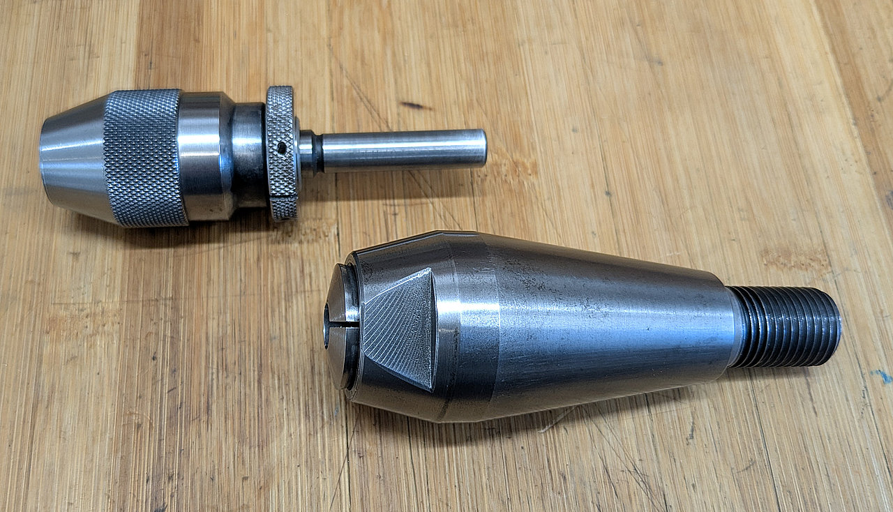
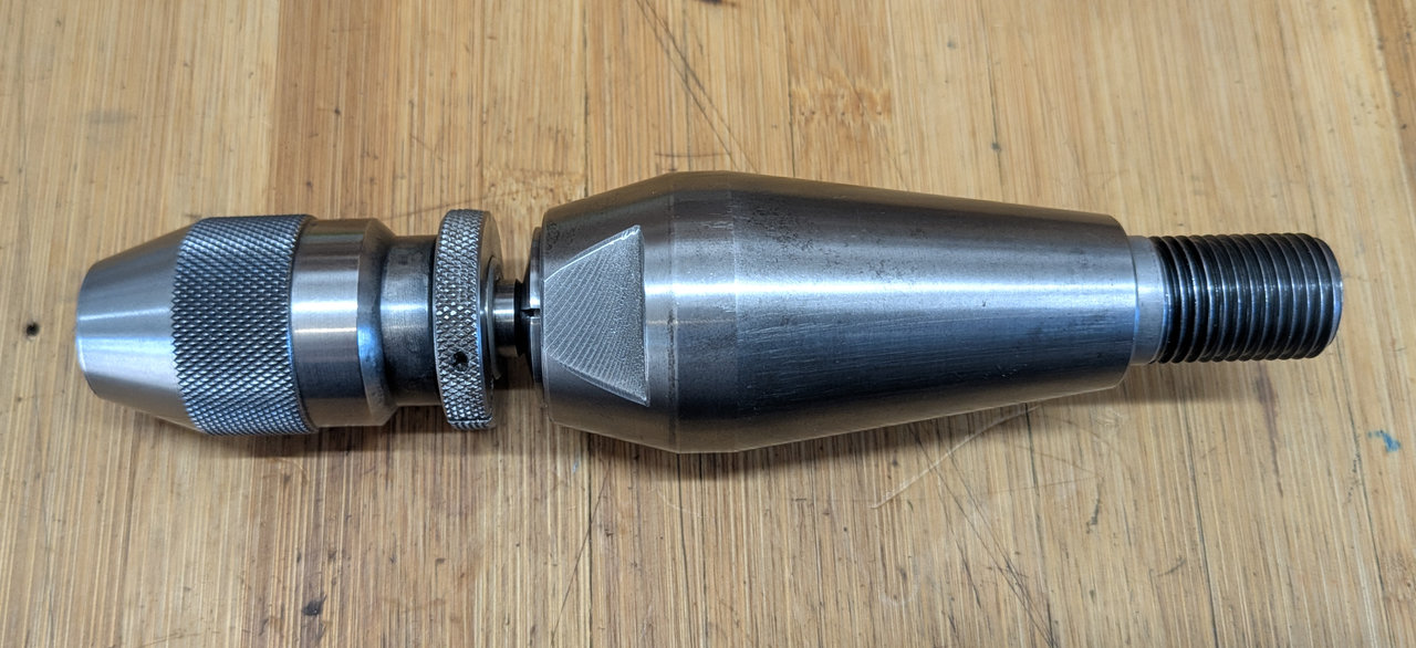
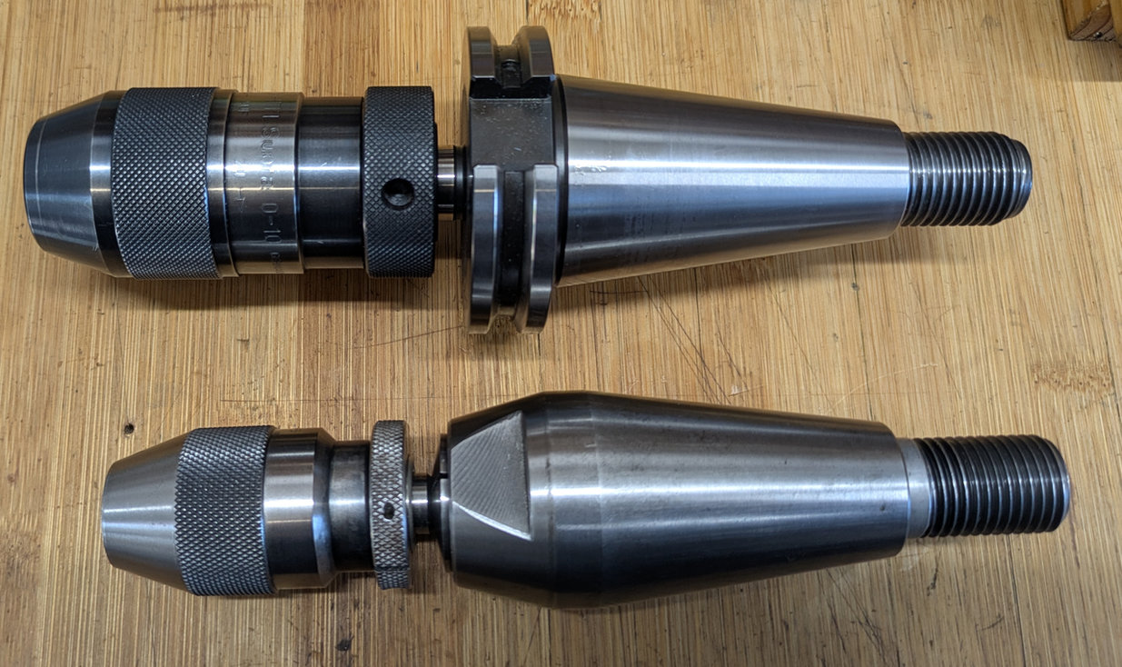
The combination is also shorter than a regular full-sized 10mm Röhm chuck on a 40 taper arbor.
So, if you do a lot of drilling in that diameter range, I can recommend this very much.
355E Collets and Reducer sleeve
Scan from the Deckel Accessoires catalogue: